Cirrus Logic CDB61584A User Manual
Dual line interface unit, Features, Description
Copyright
Cirrus Logic, Inc. 1998
(All Rights Reserved)
CDB61584A
Product Databook
Dual Line
Interface Unit
FEATURES
■
Socketed CS61584A Dual Line Interface
■
All Required Components for CS61584A
Evaluation
■
Locations to Evaluate Protection Circuitry
■
LED Status Indications for Alarm Conditions
■
Support for Hardware and Host Modes
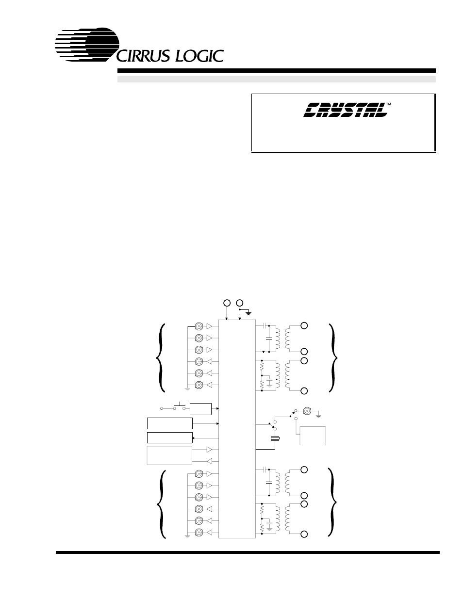
DESCRIPTION
The evaluation board includes a socketed CS61584A
dual line interface device and all support components
necessary for evaluation. The board is powered by an
external +5 Volt supply.
The board may be configured for 100
Ω
twisted-pair T1,
75
Ω
coax E1, or 120
Ω
twisted-pair E1 operation. Bind-
ing posts and bantam jacks are provided for line
interface connections. Several BNC connectors provide
clock and data I/O at the system interface. Reference
timing may be derived from a quartz crystal, crystal os-
cillator, or an external reference clock. Four LED
indicators monitor device alarm conditions.
ORDERING INFORMATION:
CDB61584A
Oscillator
Circuit
TTIP1
TRING1
RTIP1
RRING1
TTIP2
TRING2
RTIP2
RRING2
CHANNEL 1
CHANNEL 2
5V+ 0V
TCLK1
TPOS1
(TDATA1)
TNEG1
RCLK1
RPOS1
(RDATA1)
RNEG1
(BPV1)
CHANNEL 1
RESET
CIRCUIT
V+
TCLK2
TPOS2
(TDATA2)
TNEG2
RCLK2
RPOS2
(RDATA2)
RNEG2
(BPV2)
CHANNEL 2
Hardware Control
and Mode Circuit
LED Status
Indicators
Serial Interface
Control Circuit
CS61584A
XTL
REFCLK
DS261DB2 MAR ‘98
Document Outline
- CDB61584A
- FEATURES
- DESCRIPTION
- POWER SUPPLY
- BOARD CONFIGURATION
- TRANSMIT CIRCUIT
- RECEIVE CIRCUIT
- REFERENCE CLOCK
- BUFFERING
- JTAG ACCESS
- TRANSFORMER SELECTION
- LINE PROTECTION EVALUATION
- PROTOTYPING AREA
- EVALUATION HINTS
- Figure 1. Channel 1 Circuitry
- Figure 2. Channel 2 Circuitry
- Figure 3. Control Circuitry
- Figure 4. Timing Circuitry
- Figure 5. Common Circuitry