Figure 4. resistive divider for very high voltage, Summary, An158 – Cirrus Logic AN158 User Manual
Page 3
AN158
AN158REV1
3
SUMMARY
CVF current is a sampling current caused by a ca-
pacitive-based sampler. A sample capacitor is
charged with a voltage when a sample is taken. The
CVF current which flows is determined by the
equation I= CVF, where C is the value of the sam-
pling capacitor, V is the voltage magnitude being
sampled with the capacitor, and F is the sampling
frequency. An ADC with low input CVF current
will exhibit a high input impedance. A high input
impedance allows for a high source impedance
from the signal to be converted. In this applications
note example, high voltages can be measured using
a simple high resistance ratio voltage divider.
Refer to Applications Note 30, “Switched-Capaci-
tor A/D Converter Input Structures”, as it further
discusses the magnitude of CVF currents for differ-
ent switched-capacitor input structures. Also, refer
to Applications Note 152, “Using the CS552x’s
Charge Pump Drive for External Loads”, for more
details on using the CS552x’s charge pump to drive
external loads.
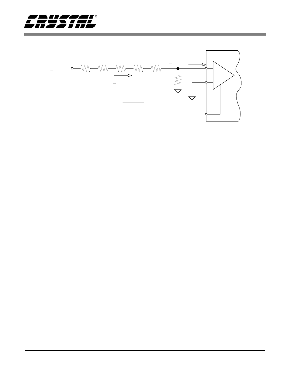
+ 100
µ
A
1 K
+ 300 pA max
300 pA
100
µ
A
= 0.0003 %
+ 1000 V
PGIA
+
-
NBV
2 M
Ω
PGIA set for ± 100 mV
2 M
Ω
2 M
Ω
2 M
Ω
2 M
Ω
-2.1 V
Figure 4. Resistive Divider for Very High Voltage