4 digital section, 1 serial port selection, Figure 5. mcu connection window – Cirrus Logic CDB5480U User Manual
Page 8: Cdb5480u
CDB5480U
8
DS893DB5
1.4
Digital Section
The digital section contains the microcontroller, USB interface, LCD, optical isolation, JTAG header, reset
circuitry, and external interface headers (J17 and J19). The microcontroller interfaces the UART or SPI of
the CS5480 with the USB connection to the PC, enabling the GUI software to access all of the CS5480
registers and functions.
1.4.1
Serial Port Selection
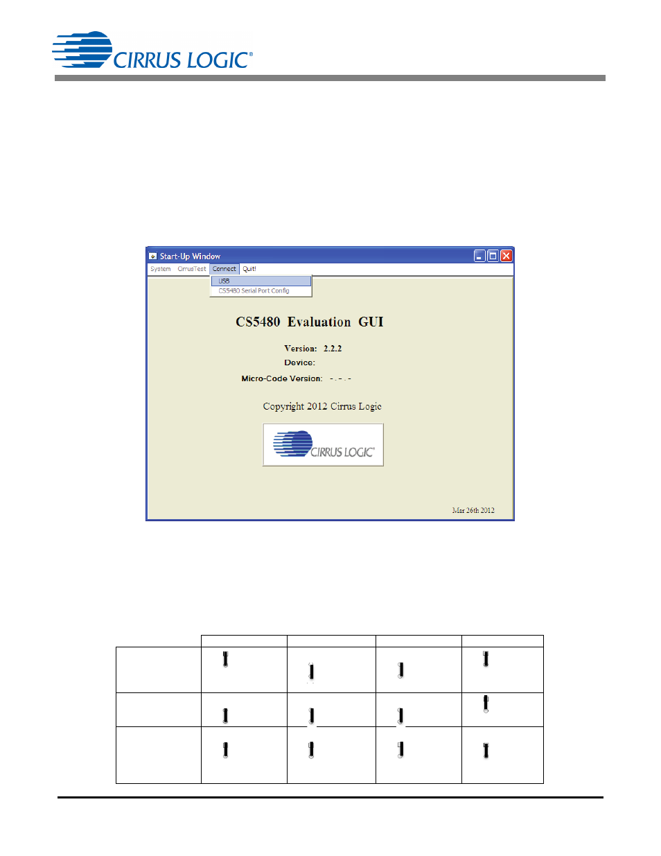
Communication to the CS5480 is provided through two serial port options — UART or SPI. It is necessary
to establish communication with the MCU before establishing a serial port communication protocol with
the CS5480 (see Figure 5).
Figure 5. MCU Connection Window
For UART communication, place the SSEL jumper to the UART position via J16, and select UART in the
serial port selection window. To enable SPI communications, place the SSEL jumper to the SPI position
via J16 and select SPI in the serial port selection window. Table 3 provides the serial communication
options on the CDB5480U board.
Table 3. Serial Communication Options
J16
J18
J20
J50
UART
Ƒ UART
ż SSEL
ż SPI
(default)
Ƒ OPTO
ż RX
ż DIGITAL
(default)
Ƒ OPTO
ż TX
ż DIGITAL
(default)
Ƒ VDDA
ż EN2
ż GND
(default)
SPI
Ƒ UART
ż SSEL
ż SPI
Ƒ OPTO
ż RX
ż DIGITAL
Ƒ OPTO
ż TX
ż DIGITAL
Ƒ VDDA
ż EN2
ż GND
Low speed
UART
(4800 Baud Max)
Ƒ UART
ż SSEL
ż SPI
Ƒ OPTO
ż RX
ż DIGITAL
Ƒ OPTO
ż TX
ż DIGITAL
Ƒ VDDA
ż EN2
ż GND