1 line voltage sensor, 2 shunt current resistor, Crd5490-z – Cirrus Logic CRD5490 User Manual
Page 5
CRD5490-Z
DS988RD1
5
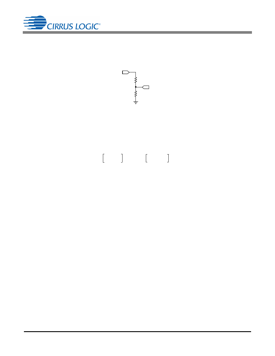
2.1 Line Voltage Sensor
The high-voltage AC line is attenuated using a voltage divider sensor comprised of five 1206 resistors before being
supplied to the CS5490 voltage channel input. Figure 2 shows the resistor diagram for line voltage sensing. R1 is
actually four large-value resistors, which increases the voltage rating. R2 is one 1K sense resistor. Refer to the
vendor’s specifications for voltage compliance.
The divider ratio is determined by the maximum input range of the CS5490 voltage channel (176mV
RMS
) and the
maximum line voltage. The division ratio is determined by Equation 1.
For a line voltage, V
IN
= 260V
RMS
, and R2 = 1K, R1 can be solved. See Equation 2:
To give a 115% margin and to select common resistor values, R1 = 115%
1.47M is selected and composed of
four resistors: 4
422k.
The voltage sense resistor (R2) must be referenced to the same potential as the current sensor and CS5490 power
supply (located either on the Line or Neutral). By design, the CRD5490-Z is referenced to the Line side after the
fuse. To switch the sensor reference, Line and Neutral of both the load and the source could be switched, and the
fuse should be placed on the line externally.
2.2 Shunt Current Resistor
The CRD5490-Z implements current sensing using a low-resistance shunt. When a shunt is used, the current
channel’s signal amplitude will be set by the shunt resistor using Ohm's Law, V = IR. To keep power dissipation low,
it is necessary to use a low-resistance shunt. The current channel of the CS5490 provides a high gain setting (50x)
to enable the use of a low-valued shunt. The maximum input amplitude for the current channel is 35mV
RMS
in the
50x gain range.
Applying Ohm's law, V
OUT
= I
SHUNT
R
SHUNT
, use Equation 3 to solve for R
SHUNT
:
To give an 85% margin, the shunt should be reduced by R
SHUNT
= 85%
2.35m = 2m. The power rating of the
shunt should be at least twice the power dissipation on the shunt with the maximum continuous load current. With
a maximum 15A load current, the CRD5490-Z uses a 2W shunt resistor.
R1
R2
VOUT
VIN
Figure 2. Voltage Sensor Attenuator
V
OUT
V
IN
R2
R1 R2
+
----------------------
176mV
RMS
=
Eq. 1
R1
R2
V
IN
V
OUT
-------------- 1
–
1000
260V
176mV
------------------- 1
–
1.47M
=
=
=
Eq. 2
R
SHUNT
V
OUT
I
SHUNT
-------------------
35.36mV
15A
------------------------
2.35m
=
=
=
Eq. 3