2 adc configuration tab, Figure 2. adc configuration tab, Figure 2.adc configuration tab – Cirrus Logic CDB53L21 User Manual
Page 9: Section 2.2, Cdb53l21
DS700DB1
9
CDB53L21
2.2
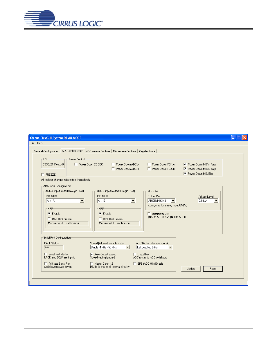
ADC Configuration Tab
The “ADC Configuration” tab provides high-level control of all setup configurations for the CS53L21. Status
text detailing the ADC’s specific configuration is shown in parenthesis or appears directly below the associ-
ated control. This text will change depending on the setting of the associated control. A description of each
control group is outlined below (a description of each register is included in the CS53L21 data sheet):
Power Control - Includes all register controls for powering down specific circuits within the CS53L21.
ADC input Configuration - Includes controls for the internal MUX, analog input, microphone bias output and
channel mix.
Serial Port Configuration - Includes controls for all settings related to the transmission and relationship of
data and clocks within the CS53L21.
Update - Reads all registers in the CS53L21 and reflects the current values in the GUI.
Reset - Resets the CS53L21.
Figure 2. ADC Configuration Tab