6 switching characteristics- reset, 7 switching characteristics - xti, Figure 1. reset timing figure 2. xti timing – Cirrus Logic CS48DV2B User Manual
Page 12: Confidenti a l dra ft d elphi
CS48DV2B Data Sheet
32-bit Audio DSP for Dedicated Dolby Volume and Audistry by Dolby
12
Copyright 2009 Cirrus Logic
DS875F2
CONFIDENTIAL
CONFIDENTI
A
L
DRA
FT
D
ELPHI
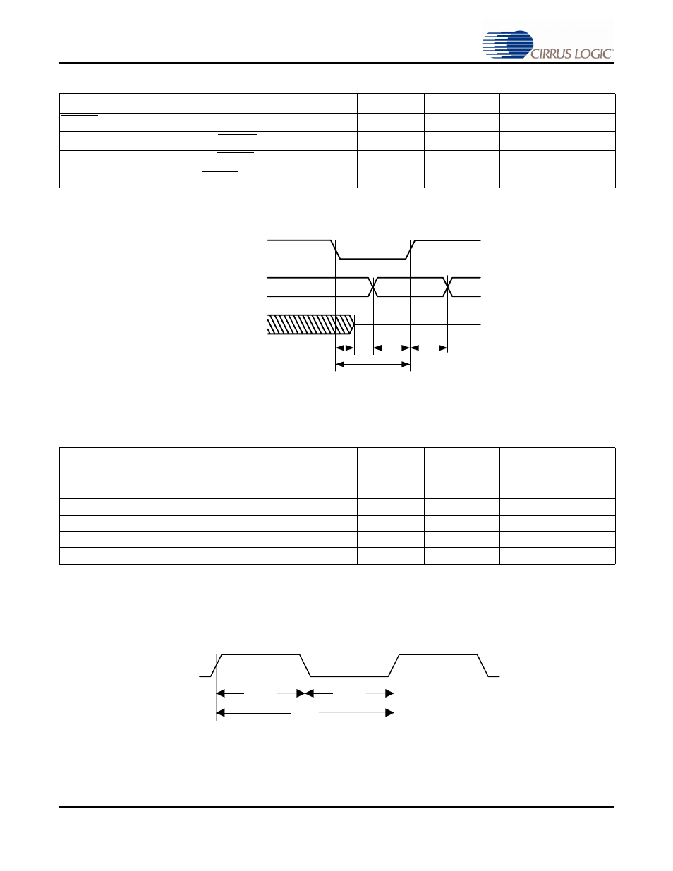
5.6 Switching Characteristics— RESET
Figure 1. RESET Timing
5.7 Switching Characteristics — XTI
Figure 2. XTI Timing
Parameter
Symbol
Min
Max
Unit
RESET minimum pulse width low
T
rstl
1
-
ms
All bidirectional pins high-Z after RESET low
T
rst2z
-
100
ns
Configuration pins setup before RESET high
T
rstsu
50
-
ns
Configuration pins hold after RESET high
T
rsthld
20
-
ns
Parameter
Symbol
Min
Max
Unit
External Crystal operating frequency
1
1. Part characterized with the following crystal frequency values: 11.2896, 12.288, 18.432, 24.576, & 27 MH.z
F
xtal
11.2896
27
MHz
XTI period
T
clki
33.3
100
ns
XTI high time
T
clkih
13.3
-
ns
XTI low time
T
clkil
13.3
-
ns
External Crystal Load Capacitance (parallel resonant)
2
2. C
L
refers to the total load capacitance as specified by the crystal manufacturer. Crystals that require a C
L
outside this range should
be avoided. The crystal oscillator circuit design should follow the crystal manufacturer’s recommendation for load capacitor
selection.
C
L
10
18
pF
External Crystal Equivalent Series Resistance
ESR
50
Ω
RESET
T
rst2z
T
rstl
T
rstsu
T
rsthld
HS[3:0]
All Bidirectional
Pins
t
clkih
t
clkil
T
clki
XTI