3 i·s data format, Figure5 standard i·s format, Time alignment – Cirrus Logic AN282 User Manual
Page 4: Figure6 left/right sample pairs in time alignment, An282, 3 i²s data format
4
AN282REV1
AN282
2.3
I²S Data Format
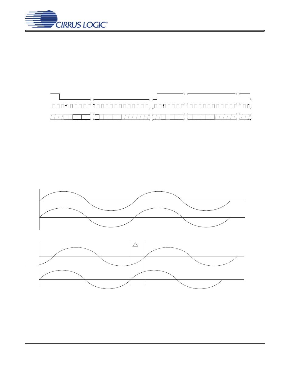
The “Inter-IC Sound” bus (I²S) format was originally developed and standardized by Philips Electronics. The Philips
I²S specification can be found at
.
, it is relatively apparent that there are significant differences between I²S and the other formats.
While I²S retains the word-length independence of the Left-Justified format, notice that the left channel of data is
framed by the low time of the Left/Right Clock and the right channel is framed by the high time. Another significant
difference is that the MSB of the audio word is shifted or delayed one period of the Serial Clock from the leading
edge of the Left/Right Clock.
Figure 5 Standard I²S Format
3. TIME ALIGNMENT
A very important aspect of the Serial Audio Interface is the fact that the left/right sample pairs represent
simultaneously sampled data or time-aligned data. Another way to look at this relationship is shown in
, where the same signal is connected to both inputs of an Analog-to-Digital converter. Analyzing the
data in left/right sample pairs shows that the left and right channels are time-aligned. However, if the data
is analyzed as right/left sample pairs, the signals appear to be time-shifted in relation to each other by
∆T,
as shown in
, where
∆T is equivalent to 1 period of the audio system sample rate.
Figure 6 Left/Right Sample Pairs in Time Alignment
Figure 7 Right/Left Sample Pair in Time Misalignment
L R C K
S C L K
L e f t C h a n n e l
R i g h t C h a n n e l
SDATA
+3
+2
+1
+5
+4
-1
-2
-3
-4
-5
+3
+2
+1
+5
+4
-1
-2
-3
-4
MSB
MSB
LSB
LSB
T