The serial audio interface, Figure2 generic serial audio interface diagram, 1 left/right clock – Cirrus Logic AN282 User Manual
Page 2: 2 serial audio data, 3 serial clock, An282 1. the serial audio interface
2
AN282REV1
AN282
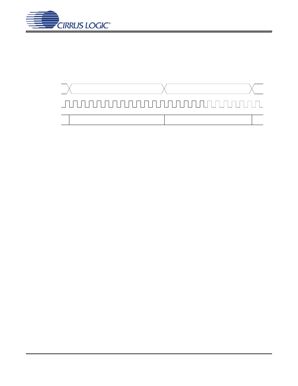
1. THE SERIAL AUDIO INTERFACE
The Serial Audio Interface is comprised of two control clocks, the Left / Right and Serial Clocks, and the Serial audio
data line. Despite the many different names used for the various clocks, their uses and requirements are nearly iden-
tical. A generalized Serial Audio Interface is shown in
. Some form of this diagram can probably be found
in every audio converter and DSP data sheet that has ever been published.
Figure 2 Generic Serial Audio Interface Diagram
1.1
Left/Right Clock
The Left/Right (LRCK) Clock is known by several names, including Word Clock, Frame Clock, Frame Sync,
and probably several others. Despite the different names, the use and requirements for this clocking signal
are identical. In all applications, the function of this clock signal to identify the audio system sample rate and
frame the two channels of audio data that exist on the single audio data line. As a result of the first men-
tioned function, the required frequency of the Left/Right Clock signal is always at the system audio sample
rate, such as 44.1 kHz, 48 kHz, etc. The high and low times of this clock are used to separate or delineate
the Left and Right channel data.
1.2
Serial Audio Data
The industry standard for representing Pulse-Coded-Modulation (PCM) audio data is a word comprised of
16 to 32 bits (16- and 24-bit data are the most common) coded in a two’s-complement format. The audio
data word is always transmitted with the Most Significant Bit (MSB) first. The only common exception to the
two’s-complement format is when the audio data is represented in one of the many compressed audio for-
mats.
1.3
Serial Clock
The Serial Clock (SCLK) is also often referred to as the Bit Clock. As with the Left/Right Clock, the function
is the same regardless of the name. The sole purpose of the Serial Clock is to shift the audio data into or
out of the serial audio port. The minimum required frequency for the Serial Clock is directly proportional to
the system audio sample rate and the audio word length. Recall that there are two channels of audio data
presented in each period of the Left/Right Clock, and the frequency of the Left/Right Clock must be at the
audio sample rate. Therefore, the minimum required Serial Clock frequency is twice the audio sample rate
times the number of bits in each audio word.
Left/Right Clock
Serial Clock
Audio Data
Audio Data