Cirrus Logic CS4352 User Manual
192 khz stereo dac with 2 vrms line out, Cs4352, Features
Copyright
© Cirrus Logic, Inc. 2007
(All Rights Reserved)
192 kHz Stereo DAC with 2 Vrms Line Out
Features
Multi-bit Delta-Sigma Modulator
24-Bit Resolution
Supports Sample Rates up to 192 kHz
106 dB A-wt Dynamic Range
-93 dB THD+N
Integrated Line Driver
2 Vrms Output into 5 k
Ω AC Load
Analog Low-Pass Filter
Stereo Mutes with Auto-Mute Function
Low Clock-Jitter Sensitivity
Low-Latency Digital Filtering
Popguard
®
Technology for Control of Clicks
and Pops
Single-Ended Outputs
+3.3 V Core, +9 to 12 V Analog, and +1.5 to
3.3 V Interface Power Supplies
Low Power Consumption
20-pin TSSOP, Lead-Free Assembly
Description
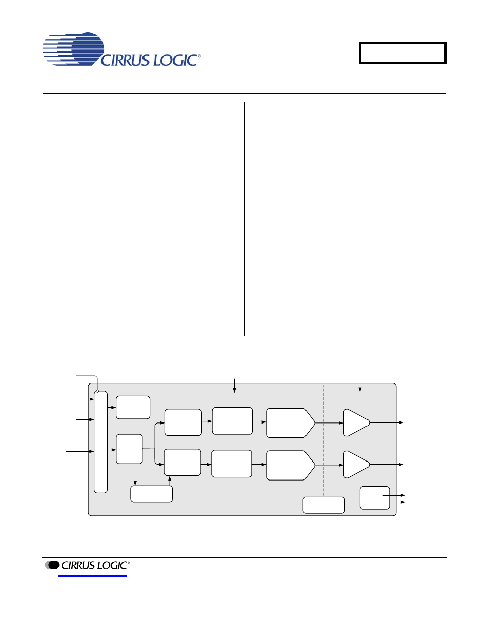
The CS4352 is a complete stereo digital-to-analog sys-
tem including digital interpolation, fifth-order multi-bit
delta-sigma digital-to-analog conversion, digital de-em-
phasis, analog filtering, and on-chip 2 Vrms line-level
driver. The advantages of this architecture include ideal
differential linearity, no distortion mechanisms due to re-
sistor matching errors, no linearity drift over time and
temperature, high tolerance to clock jitter, and a minimal
set of external components.
The CS4352 is available in a 20-pin TSSOP package in
both Commercial grade (-40°C to +85°C) and Automo-
tive grade (-40°C to +105°C). The CDB4352 Customer
Demonstration Board is also available for device evalu-
ation and implementation suggestions. Please see
“Ordering Information” on page 20
for complete details.
These features are ideal for cost-sensitive, 2-channel
audio systems including video game consoles, DVD
players, A/V receivers, set-top boxes, digital TVs and
DVD Recorders, mini-component systems, and mixing
consoles.
PCM
Serial
Interface
Interpolation
Filter
Serial Audio Input
Left and Right
Mute Controls
2 Vrms Line Level
Right Channel
Output
2 Vrms Line Level
Left Channel
Output
Reset
1.5 V to 3.3 V
Hardware
Configuration
Leve
l Transl
a
to
r
Hardware Control
Multibit
∆Σ Modulator
3.3 V
9 V to 12 V
Interpolation
Filter
Amp
+
Filter
Amp
+
Filter
Multibit
∆Σ Modulator
Auto Speed Mode
Detect
DAC
DAC
External
Mute
Control
Internal Voltage
Reference
JUN '07
DS684F2
CS4352
Confidential Draft
6/18/07
Document Outline
- 1. Pin Descriptions
- 2. Characteristics and Specifications
- Recommended Operating Conditions
- Absolute Maximum Ratings
- DAC Analog Characteristics - COMMERCIAL (-CZZ)
- DAC Analog Characteristics - AUTOMOTIVE (-DZZ)
- Combined Interpolation & On-chip Analog Filter Response
- Switching Specifications - Serial Audio Interface
- Digital Characteristics
- Power and Thermal Characteristics
- 3. Typical Connection Diagram
- 4. Applications
- 5. Digital Filter Response Plots
- Figure 7. Single-Speed Stopband Rejection
- Figure 8. Single-Speed Transition Band
- Figure 9. Single-Speed Transition Band (detail)
- Figure 10. Single-Speed Passband Ripple
- Figure 11. Double-Speed Stopband Rejection
- Figure 12. Double-Speed Transition Band
- Figure 13. Double-Speed Transition Band (detail)
- Figure 14. Double-Speed Passband Ripple
- Figure 15. Quad-Speed Stopband Rejection
- Figure 16. Quad-Speed Transition Band
- Figure 17. Quad-Speed Transition Band (detail)
- Figure 18. Quad-Speed Passband Ripple
- 6. Parameter Definitions
- 7. Package Dimensions
- 8. Ordering Information
- 9. Revision History