Register description, E mclk control (address 00h) register, Mode control (address 01h) bits se – Cirrus Logic CS4341 User Manual
Page 25: Section 6.2.1 a, Section 6). the, Cs4341
CS4341
DS298F5
25
6. REGISTER DESCRIPTION
NOTE: All registers are read/write in I²C Mode and write only in SPI mode, unless otherwise stated.
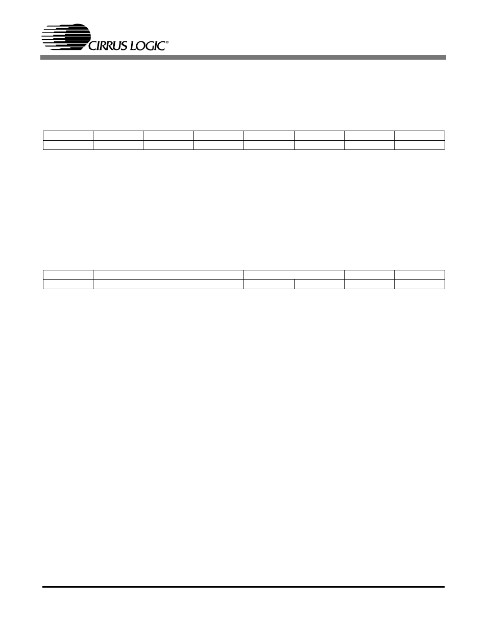
6.1
MCLK CONTROL (ADDRESS 00H)
6.1.1 MCLK DIVIDE-BY-2 (MCLKDIV)
BIT 1
Default = 0
0 - Disabled
1 - Enabled
Function:
The MCLKDIV bit enables a circuit which divides the externally applied MCLK signal by 2.
6.2
MODE CONTROL (ADDRESS 01H)
6.2.1 AUTO-MUTE (AMUTE)
BIT 7
Default = 1
0 - Disabled
1 - Enabled
Function:
The Digital-to-Analog converter output will mute following the reception of 8192 consecutive audio
samples of static 0 or -1. A single sample of non-zero data will release the mute. Detection and muting
is done independently for each channel. The quiescent voltage on the output will be retained and the
Mute Control pin will go active during the mute period. The muting function is affected, similar to vol-
ume control changes, by the Soft and Zero Cross bits in the Transition and Mixing Control (address
02h) register.
7
6
5
4
3
2
1
0
Reserved
Reserved
Reserved
Reserved
Reserved
Reserved
MCLKDIV
Reserved
0
0
0
0
0
0
0
0
7
6
5
4
3
2
1
0
AMUTE
DIF2
DIF1
DIF0
DEM1
DEM0
POR
PDN
1
0
0
0
0
0
1
1