Cirrus Logic CS4341 User Manual
Bit, 96 khz stereo dac with volume control, Cs4341, Features
1
Copyright
© Cirrus Logic, Inc. 2005
(All Rights Reserved)
24-Bit, 96 kHz Stereo DAC with Volume Control
Features
!
101 dB Dynamic Range
!
-91 dB THD+N
!
+3.0 V or +5.0 V Power Supply
!
Low Clock-Jitter Sensitivity
!
Filtered Line-Level Outputs
!
On-Chip Digital De-Emphasis for 32, 44.1
and 48 kHz
!
ATAPI Mixing
!
Digital Volume Control with Soft Ramp
– 94 dB Attenuation
– 1 dB Step Size
– Zero Crossing Click-Free Transitions
!
Popguard
®
Technology for Control of Clicks
and Pops
!
33 mW with 3.0 V Supply
Description
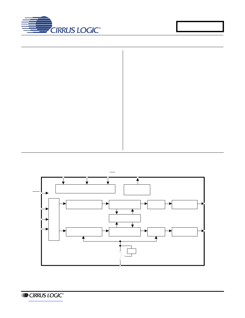
The CS4341 is a complete stereo digital-to-analog sys-
tem including digital interpolation, fourth-order Delta-
Sigma digital-to-analog conversion, digital de-emphasis
and switched capacitor analog filtering. The advantages
of this architecture include: ideal differential linearity, no
distortion mechanisms due to resistor matching errors,
no linearity drift over time and temperature and a high
tolerance to clock jitter.
The CS4341 accepts data at audio sample rates from
4 kHz to 100 kHz, consumes very little power, and oper-
ates over a wide power supply range. The features of
the CS4341 are ideal for DVD players, CD players, set-
top box and automotive systems.
ORDERING INFORMATION
CS4341-KS
16-pin SOIC, -10 to 70 °C
CS4341-CZZ, Lead Free
16-pin TSSOP, -10 to 70 °C
CDB4341
Evaluation Board
I
Volume Control
Interpolation Filter
∆Σ DAC
Analog Filter
Control Port
Volume Control
Interpolation Filter
Analog Filter
Ser
ial
Po
rt
SCL/CCLK
MUTEC
AD0/CS
AOUTA
AOUTB
RST
LRCK
SDATA
MCLK
SDA/CDIN
∆Σ DAC
External
Mute Control
SCLK
Mixer
÷2
DECEMBER '05
DS298F5
CS4341
Document Outline
- Features
- Description
- 1. Characteristics and Specifications
- Specified Operating Conditions
- Absolute Maximum Ratings
- Analog Characteristics (CS4341-KS/CZZ)
- Combined Interpolation & On-Chip Analog Filter Response
- Figure 3. Single-Speed Stopband Rejection
- Figure 4. Single-Speed Transition Band
- Figure 5. Single-Speed Transition Band (Detail)
- Figure 6. Single-Speed Passband Ripple
- Figure 7. Double-Speed Stopband Rejection
- Figure 8. Double-Speed Transition Band
- Figure 9. Double-Speed Transition Band (Detail)
- Figure 10. Double-Speed Passband Ripple
- Switching Specifications - Serial Audio Interface
- Switching Characteristics - Internal Serial Clock
- Switching Characteristics - Control Port Interface (I·C®)
- Switching Characteristics - Control Port Interface (SPI™)
- DC Electrical Characteristics
- Digital Input Characteristics
- Digital Interface Specifications
- 2. Pin Description
- 3. Typical Connection Diagram
- 4. Applications
- 4.1 Sample Rate Range/Operational Mode
- 4.2 System Clocking
- 4.3 Digital Interface Format
- 4.4 De-Emphasis
- 4.5 Power-Up Sequence
- 4.6 Popguard® Transient Control
- 4.7 Mute Control
- 4.8 Grounding and Power Supply Arrangements
- 4.9 Control Port Interface
- 5. Register Quick Reference
- 6. Register Description
- 7. Parameter Definitions
- 8. Package Dimensions
- 9. Package Thermal Resistance
- 10. References
- 11. Revision History
- CS4341