Appendix c: pll filter, Figure 27. pll block diagram, 1 external filter components – Cirrus Logic CS42516 User Manual
Page 77: 1 general
DS583F2
77
CS42516
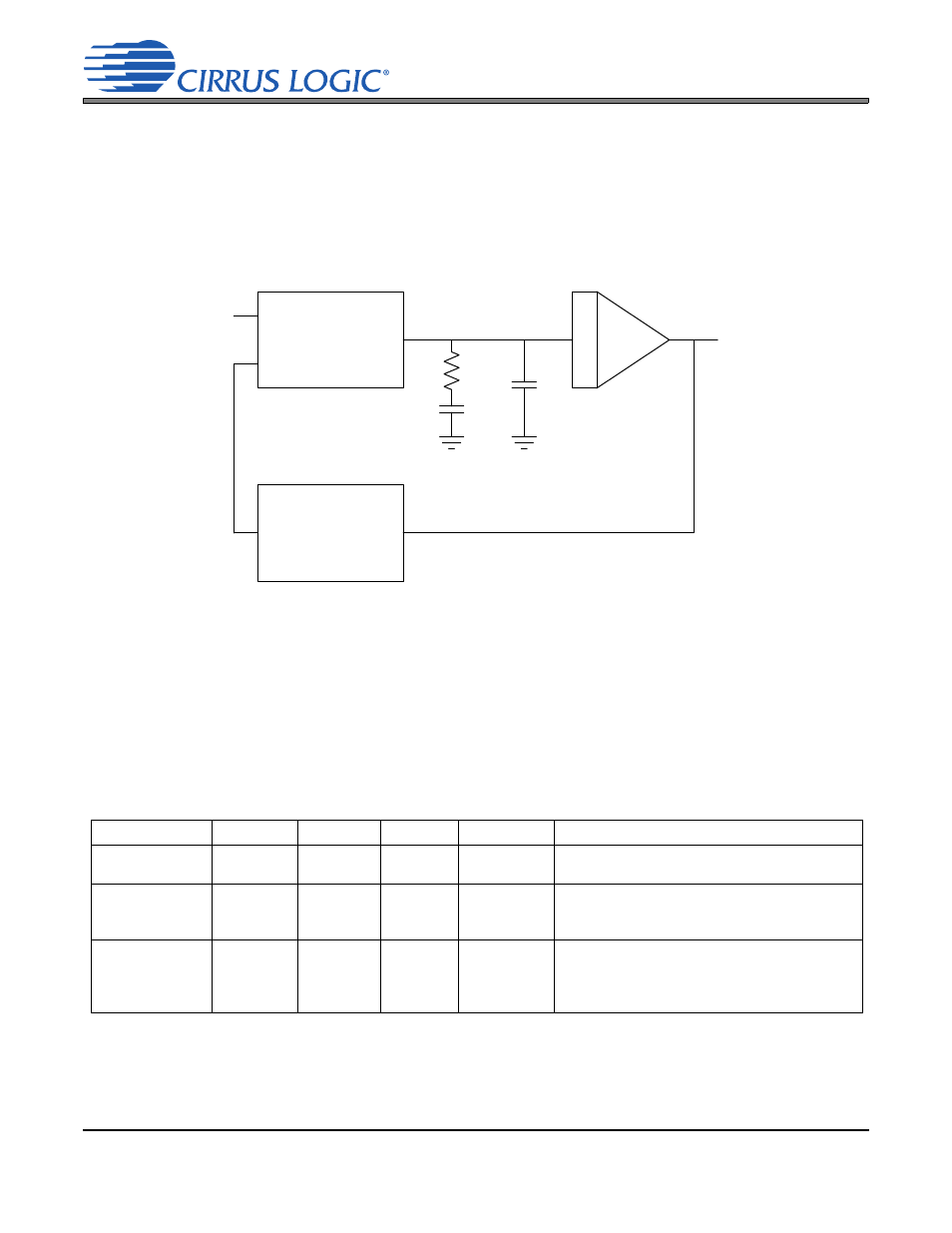
10.APPENDIX C: PLL FILTER
The PLL has been designed to only use the preambles of the S/PDIF stream to provide lock update information to
the PLL. This results in the PLL being immune to data-dependent jitter effects because the S/PDIF preambles do
not vary with the data.
The PLL has the ability to lock onto a wide range of input sample rates with no external component changes. The
nominal center sample rate is the sample rate that the PLL first locks onto upon application of an S/PDIF data
stream.
10.1 External Filter Components
10.1.1 General
The PLL behavior is affected by the external filter component values and the locking mode as configured
by the LOCKM[1:0] bits in register 24h.
shows the supported configurations of PLL component
values and their associated locking modes.
Phase
Comparator
and Charge Pump
N
VCO
RMCK
INPUT
CRIP
CFILT
RFILT
Figure 27. PLL Block Diagram
RFILT (k
) CFILT (F) CRIP (pF) LOCKM[1:0]
Notes
Configuration 1
2.55
0.047
2200
00
Used for backward compatibility with Revision C
devices.
Configuration 2
2.55
0.047
2200
01
Default configuration for Revision D devices.
Provides improved wideband jitter rejection in
Double- and Quad-Speed modes.
Configuration 3
1.37
0.022
1000
10
Provides improved in-band jitter rejection, with
increased wideband jitter. Use this configuration
for best DAC and ADC performance when
clocked from the PLL recovered clock.
Table 21. External PLL Component Values & Locking Modes