Cirrus logic audio converter tdm interface, 1 channel block, Figure6. 32-bit receiver channel block – Cirrus Logic AN301 User Manual
Page 3: 2 exceptions to the rule, An301
AN301
AN301REV1
3
2. CIRRUS LOGIC AUDIO CONVERTER TDM INTERFACE
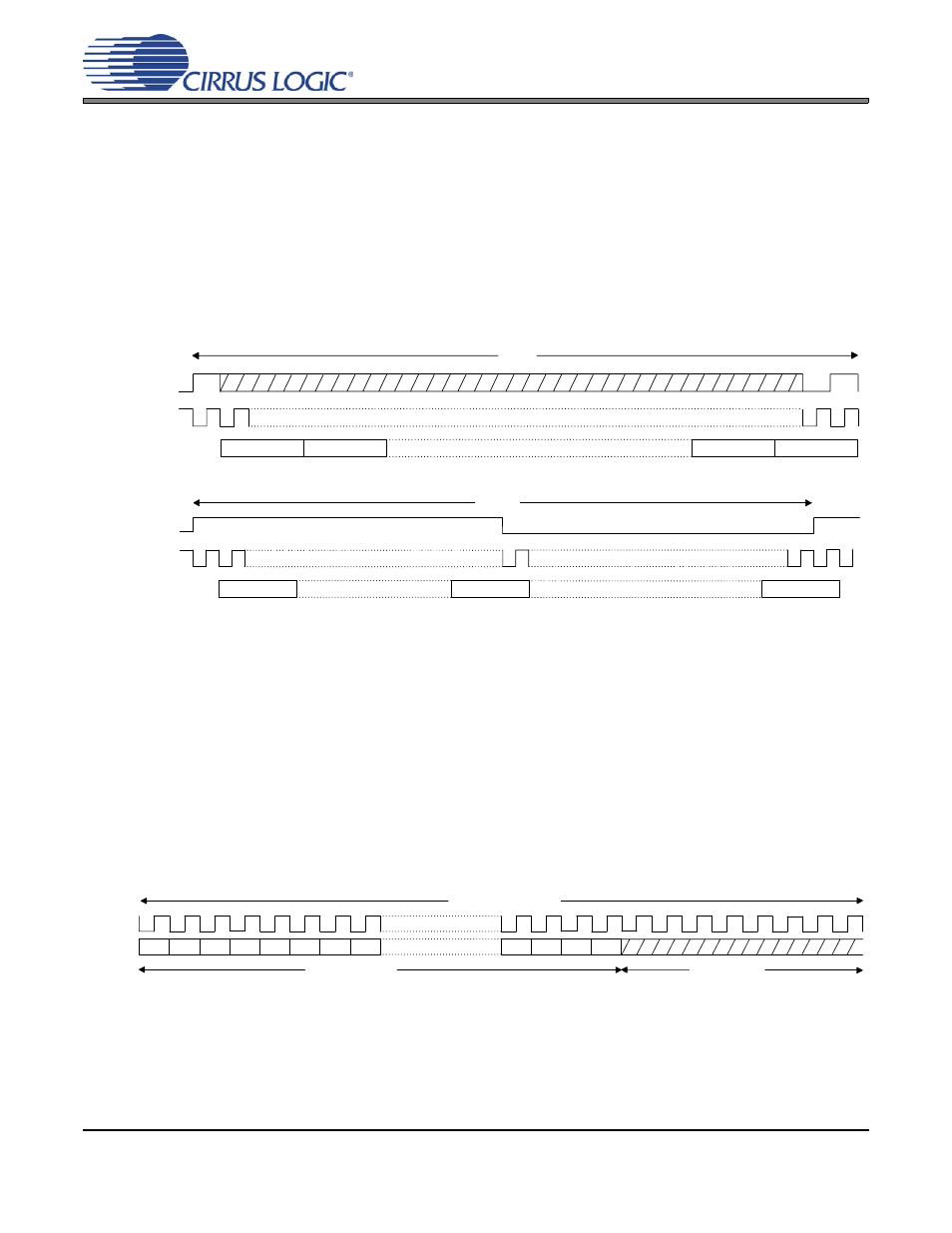
All Cirrus Logic converter products are capable as operating as a slave to a systems clock, such as a DSP generated
serial clock and FSYNC. When operating in this mode, the required pulse width of the frame sync is extremely flex-
ible, as shown in
, where the minimum high time is one period of the serial clock and the minimum low time
is also one period of the serial clock. Many Cirrus Logic products also are capable of sourcing the systems clocks
or operating as a systems clock Master. When operated in this mode the duty cycle of the FSYNC is 50% of the
frame period as shown in
.
Cirrus Logic has chosen to implement a serial port configuration where the channel block is delayed one period of
the serial clock following the rising edge of the FSYNC as shown in
. Notice that the last bit of
the Channel N block is within the FSYNC pulse of the next frame.
Figure 4. Cirrus Logic TDM System Clock Slave Format
Figure 5. Cirrus Logic TDM System Clock Master Format
2.1
Channel Block
The standard Cirrus Logic implementation for a data transmitter is a 32-bit channel block with 24-bit audio
data as previously discussed and shown in
. The standard implementation for a data receiver is a
32-bit channel block with 24-bit audio data as shown in
. Notice that the trailing 8-bit pad is not re-
quired to be zero since the receiver will ignore the trailing 8-bits.
A limited number of Cirrus Logic products support a 16-bit channel block for use with 16-bit data. Please be
aware that both the data transmitter and receiver must be configured for a 16-bit channel block. Many DSP
devices also support a 24-bit channel block which is efficient for transmitting 24-bit audio data. Unfortunate-
ly, this requires serial clocks and data rates which are asynchronous to the conversion processes in mixed-
signal products. This can degrade analog performance and, as a result, Cirrus Logic converter products do
not support a 24-bit channel block.
Figure 6. 32-Bit Receiver Channel Block
2.2
Exceptions to the Rule
Despite efforts to standardize on a TDM interface, there are occasionally situations that require deviation
from the standard, as well as legacy implementations that deviate from this format. An example is the
CS8421 Asynchronous Sample Rate Converter which can use the full 32-bit channel block for audio data.
Please refer to the product data sheet to confirm device operation.
SCLK
SDATA
Channel 1
Channel 2
Channel N-1
Channel N
FSYNC
Frame
FSYNC
SCLK
SDATA
Frame
Channel 1
Channel N
Channel N/2
MSB
32-Bit Channel Block
LSB
24-Bit Audio Word
8-Bit Pad
-1
-2
-3
-4
-5
-6
-7
+1
+2
+3