Tdm overview, Figure2. generic tdm interface, 1 channel block – Cirrus Logic AN301 User Manual
Page 2: Figure3. 32-bit channel block, 2 frame synchronization pulse, 3 channel block alignment with frame sync, 4 serial clock, An301 1. tdm overview
2
AN301REV1
AN301
1. TDM OVERVIEW
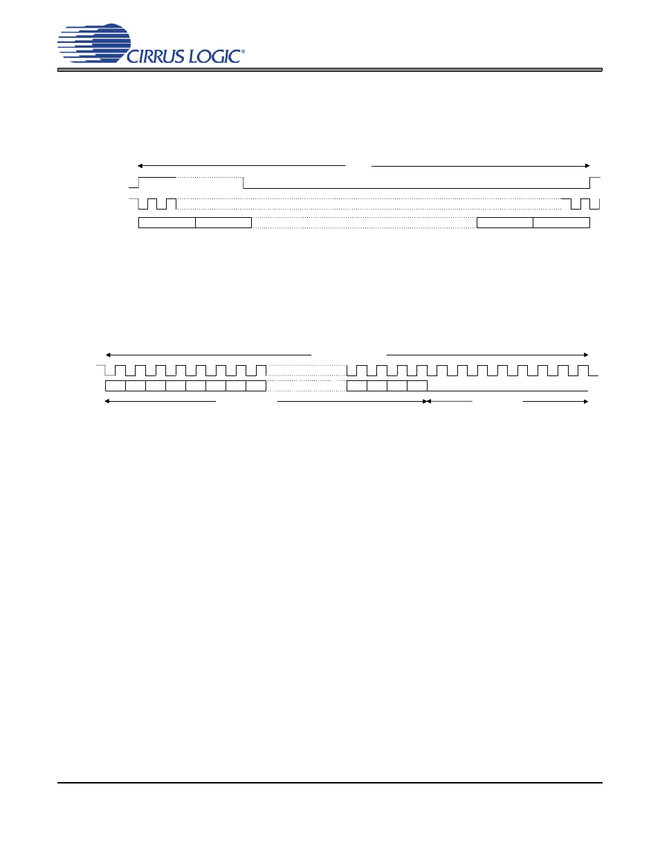
The TDM interface is similar to the 2-Channel Serial Audio Interface, discussed in Cirrus Applications Note AN282,
with the exception that more channels, typically 4, 6 or 8, are transmitted within a sample frame or sample period,
as shown in
. As with the 2-Channel Serial Audio Interface, the TDM interface is comprised of two control
clocks, a frame synchronization pulse (FSYNC) and serial clock (SCLK), and the serial audio data line (SDATA).
Figure 2. Generic TDM Interface
1.1
Channel Block
Each channel block is comprised of the audio data word followed by a sufficient number of zero data bits to
complete the N-bit channel block. The example shown in
shows a 32-bit channel block with 24-bit
audio data. Notice that the audio word is typically transmitted with the Most Significant Bit (MSB) first. The
industry standard for representing Pulse-Coded-Modulation (PCM) audio data is a 16 to 32 bit word (16-
and 24-bit are the most common) coded in a two’s-complement format.
Figure 3. 32-Bit Channel Block
1.2
Frame Synchronization Pulse
The function of the FSYNC pulse is simply to identify the beginning of a frame. The beginning is always
indicated by the rising edge of the pulse, as shown in
. Another notable point is that the frame rate
is always at the audio sample rate, such as 44.1 kHz, 48 kHz, etc.
The majority of the TDM implementations only use the rising edge of FSYNC and ignore the falling edge.
However, device product documentation often implies that the width of the pulse is important. There are two
common representations for the required width of the FSYNC pulse. The first is a frame synchronization
pulse where the width is equivalent to a channel block. The second is a pulse where the width is equivalent
to a single period of the serial clock. Unfortunately, the product documentation rarely supplies a sufficient
amount of information to determine if the falling edge is used. The safe approach is to follow the product
documentation and assume the falling edge is used or contact the manufacturer for clarification.
1.3
Channel Block Alignment with Frame Sync
There are two common options for the alignment of the first channel block and the rising edge of FSYNC.
The first is shown in
where the beginning of the channel block aligns with the rising edge of the
FSYNC. In the second option, the channel block is delayed one period of the serial clock following the rising
edge of the FSYNC.
1.4
Serial Clock
The sole purpose of the serial clock is to shift the audio data into or out of the serial audio ports. The required
frequency for the serial clock is directly proportional to the system audio sample rate, the number of channel
blocks within a frame and the bit-width of each channel block. As an example, an 8-channel frame with 32-
bit channel blocks operating at 48 kHz requires a 12.288 MHz serial clock.
SCLK
SDATA
Channel 1
Channel 2
Channel N-1
Channel N
FSYNC
Frame
MSB
32-Bit Channel Block
LSB
24-Bit Audio Word
8-Bit Zero Pad
-1
-2
-3
-4
-5
-6
-7
+1
+2
+3