Design example, Figure 4. 2-pole multiple feedback filter design, An48 – Cirrus Logic AN048 User Manual
Page 3
AN48
3
Step 6: Review the resistor and capacitor values.
It is desirable to keep the capacitor values suffi-
ciently large to minimize the effects of stray capac-
itance. It may be necessary to adjust the capacitor
values chosen in Step 4 to achieve this require-
ment. Also verify that R1 is larger than the mini-
mum required input impedance.
Step 7: The resistor values calculated in Step 5
are generally not standard values. Select standard
values which are nearest the calculated values.
This should not create a large change in the filter
characteristics since metal film resistors are avail-
able in approximately 2.5% increments which al-
lows for component selection near the calculated
values. However, it is advisable to calculate the ac-
tual filter parameters, using the selected values,
using the equations in Step 5.
Step 8: The conversion from the singled-ended cir-
cuit to the differential circuit requires duplicating
the values of R
1
, C
2
, R
3
, R
4
and C
5
in the non-in-
verting input, as shown in Figure 1.
3. Design Example
Step 1: The required pass band gain, H
o
, is -1 for
this example.
Step 2: Minimum input impedance is 10 k
Ω.
Step 3: Select a Butterworth response with a cor-
ner frequency of 50kHz. (A two-pole Butterworth
with a corner frequency of 50 kHz attenuates the
signal at 20 kHz by approximately 0.1 dB and has
nearly ideal phase linearity within the audio band.)
F
c
= 50 kHz
alpha = .7071
beta = .7071
Step 4: Select convenient values for C
5
and C
2
.
C
5
= 220 pF
C
2
= 1000 pF
Step 5: Given F
c
, H
o
, C
2
, C
5
, alpha and beta, cal-
culate R
1
, R
3
and R
4
.
R
1
= 13.77 k
Ω
R
3
= 3.343 k
Ω
R
4
= 13.77 k
Ω
Step 6: Review the filter component values and fil-
ter parameters. Verify that R
1
is greater than 10 k
Ω
and the capacitor values are sufficiently large to
negate stray capacitance effects.
Step 7: Select standard resistor values which are
nearest the calculated values.
R
1
= 13.7 k
Ω
R
3
= 3.32 k
Ω
R
4
= 13.7 k
Ω
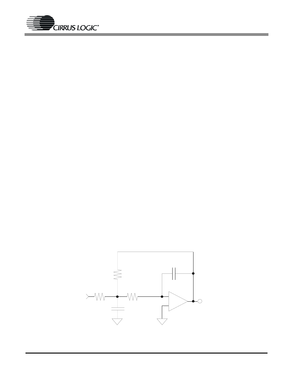
Step 8: The conversion from the singled-ended to
the differential circuit requires duplicating the val-
ues of R
1
, C
2
, R
3
, R
4
and C
5
in the non-inverting
input as shown in Figure 4 and 5.
Figure 4.
2-Pole Multiple Feedback Filter Design
_
220 pF
3.32 k
Ω
13.7 k
Ω
1000 pF
13.7 k
Ω
+