System connectors and jumpers – Cirrus Logic CRD35L01 User Manual
Page 7
DS914RD2
7
CRD35L01
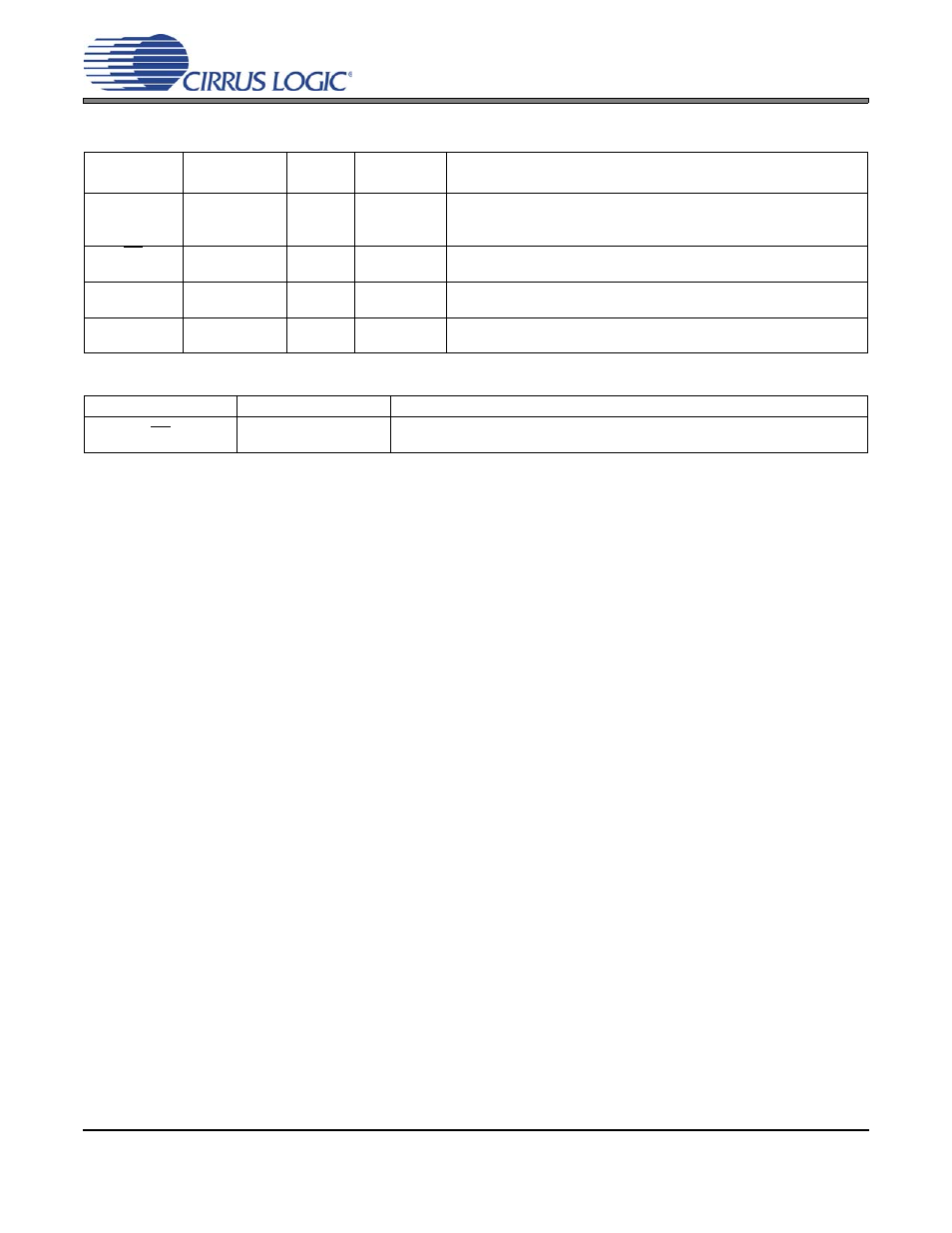
3. SYSTEM CONNECTORS AND JUMPERS
Connector
Name
Reference
Designator
Pin
Signal
Direction
Connector Function
IN+
IN-
GND
J1
J1
J1
1
2
3
Input
Input
GND
Differential analog input (+) to CS35L01.
Differential analog input (-) to CS35L01.
GND reference connection.
SD
GND
J2
J2
1
2
Input
GND
Device shutdown control.
GND reference connection.
OUT+
OUT-
J3
J3
1
2
Output
Output
Analog output (+) from CS35L01.
Analog output (-) from CS35L01.
VBATT
GND
J4
J4
1
2
Input
Input
Positive connection from power supply, +2.5 to +5.5 VDC.
GND connection from power supply.
Table 1. System Input and Output Connections
Control Name
Function
Function Selected
SD
Shutdown
Low = CS35L01 shutdown enabled
High = CS35L01 shutdown disabled
Table 2. J2 Shutdown Control Settings
See also other documents in the category Cirrus Logic Hardware:
- CobraNet (147 pages)
- CS4961xx (54 pages)
- CS150x (8 pages)
- CS1601 (2 pages)
- CS1501 (16 pages)
- CS1601 (16 pages)
- CS1610 (16 pages)
- CRD1610-8W (24 pages)
- CRD1611-8W (25 pages)
- CDB1610-8W (21 pages)
- CS1610A (18 pages)
- CDB1611-8W (21 pages)
- CDB1610A-8W (21 pages)
- CDB1611A-8W (21 pages)
- CRD1610A-8W (24 pages)
- CRD1611A-8W (25 pages)
- CS1615 (16 pages)
- AN403 (15 pages)
- AN401 (14 pages)
- AN400 (15 pages)
- AN375 (27 pages)
- AN376 (9 pages)
- CRD1615-8W (22 pages)
- CRD1616-8W (23 pages)
- AN402 (14 pages)
- AN404 (15 pages)
- CRD1615A-8W (21 pages)
- CS1615A (16 pages)
- CS1630 (56 pages)
- AN374 (35 pages)
- AN368 (80 pages)
- CRD1630-10W (24 pages)
- CRD1631-10W (25 pages)
- CS1680 (16 pages)
- AN405 (13 pages)
- AN379 (31 pages)
- CRD1680-7W (31 pages)
- AN335 (10 pages)
- AN334 (6 pages)
- AN312 (14 pages)
- AN Integrating CobraNet into Audio Products (16 pages)
- CobraNet Audio Routing Primer (9 pages)
- Bundle Assignments in CobraNet Systems (3 pages)
- CS2300-01 (3 pages)
- CS2000-CP (38 pages)