Cs3310 – Cirrus Logic CS3310 User Manual
Page 7
CS3310
DS82F1
7
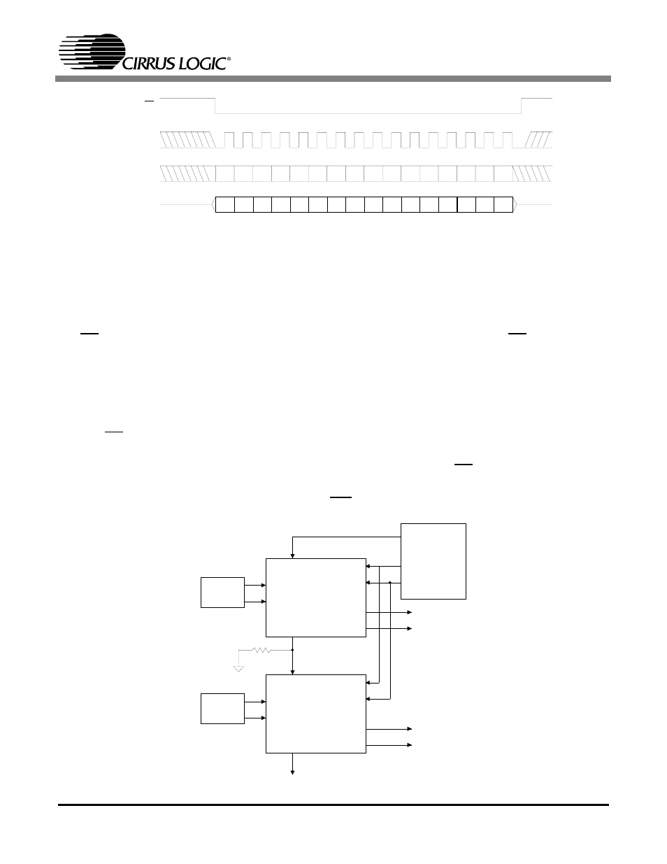
In single device operation, volume control data is loaded into the 16-bit shift register by holding
the CS pin low for sixteen SCLK pulses and then latched on the rising edge of CS. The previous
contents of the shift-register are shifted through the register and out SDATAO during the process.
Multi-channel operation can be implemented as shown in Figure 4 by connecting the SDATAO
of device #1 to the SDATAI pin of device #2. In this manner multiple CS3310s can be loaded from
a single serial data line without complex addressing schemes. Volume control data is loaded by
holding CS low for 16 x N SCLK pulses, where N is the number of devices in the chain. The 16
bits clocked into device #1 on SCLK pulses 1-16 are clocked into device #2 on SCLK pulses 17-
32. The CS3310s are simultaneously updated on the rising edge of CS following 16 x N SCLK
pulses Notice that a 47 kohm resistor is required to terminate SDATAI, as shown in Figure 4, due
to the high impedance state of SDATAO when CS is high..
R7 R6 R5 R4 R3 R2 R1 R0 L7 L6 L5 L4 L3 L2 L1 L0
R7 R6 R5 R4 R3 R2 R1 R0 L7 L6 L5 L4 L3 L2 L1 L0
CS
SCLK
SDATAI
SDATAO
L0 = Left Channel Least Significant Bit R0 = Right Channel Least Significant Bit
L7 = Left Channel Most Significant Bit R7 = Right Channel Most Significant Bit
SDATAI is latched internally on the rising edge of SCLK
SDATAO transitions after the falling edge of SCLK
SDATAO bits reflect the data previously loaded into the CS3310
Figure 3. Serial Port Timing
AUDIO
SIGNAL
16
9
AINL
AINR
SDATAI
SDATAO
AOUTL
AOUTR
CS
SCLK
CS3310
CONTROLLER
14
11
2
6
3
7
AUDIO
SIGNAL
16
9
AINL
AINR
SDATAI
SDATAO
AOUTL
AOUTR
CS
SCLK
CS3310
14
11
2
6
3
7
47 k
#1
#2
Figure 4. Daisy Chaining Diagram