Pin description, Cs3310 – Cirrus Logic CS3310 User Manual
Page 13
CS3310
DS82F1
13
PIN DESCRIPTION
Power Supply Connections
VA+ - Positive Analog Power, Pin 12.
Positive analog supply. Nominally +5 volts.
VA- - Negative Analog Power, Pin 13.
Negative analog supply. Nominally -5 volts.
AGNDL - Left Channel Analog Ground, Pin 15.
Analog ground reference for the left channel.
AGNDR - Right Channel Analog Ground, Pin 10.
Analog ground reference for the right channel.
VD+ - Positive Digital Power, Pin 4.
Positive supply for the digital section. Nominally +5 volts. Applying power to VD+ prior
to VA+ creates a SCR latch-up condition. Refer to Figure 2 for the recommended
power connections.
DGND - Digital Ground, Pin 5.
Digital ground for the digital section.
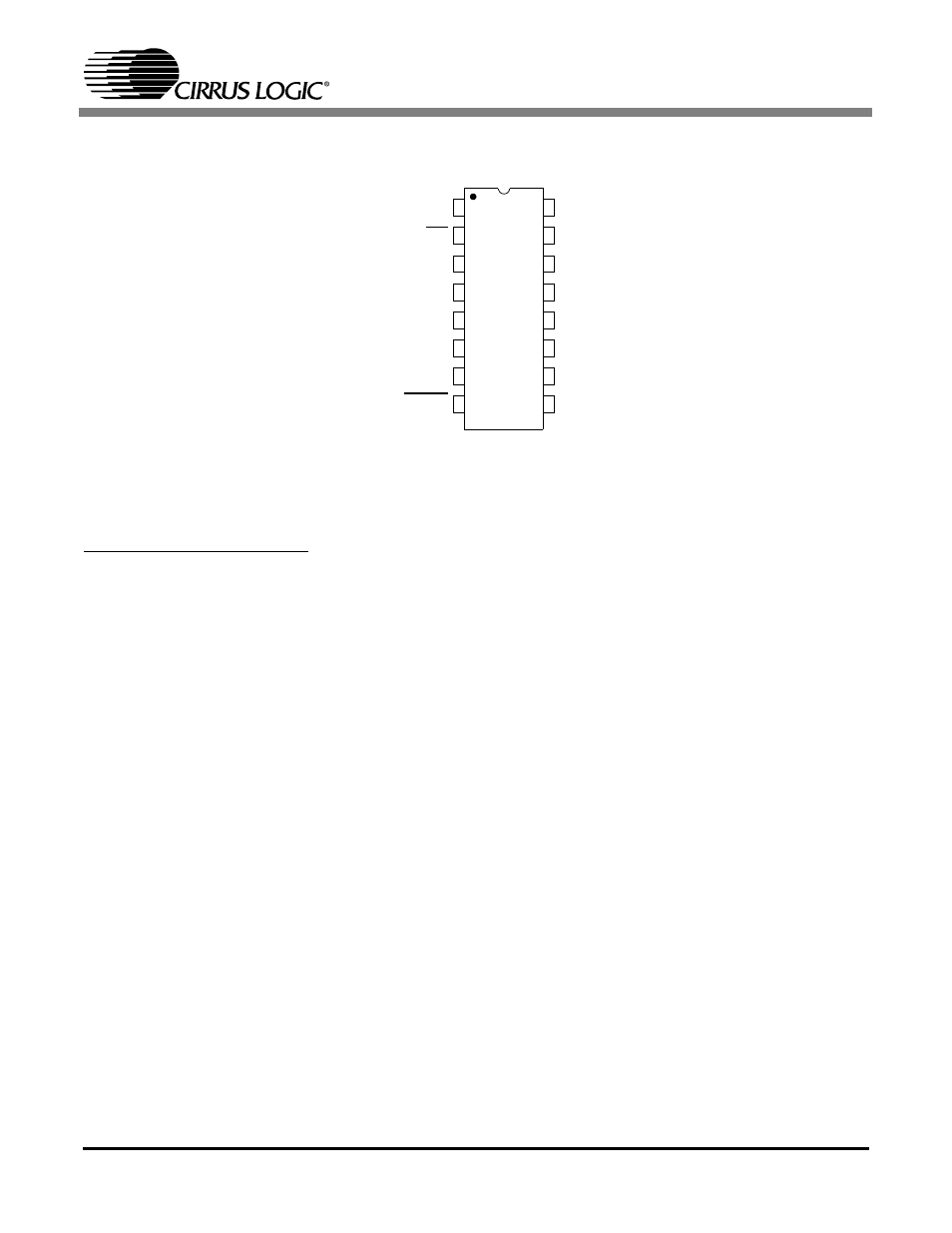
Zero Crossing Enable
ZCEN
AINL
Left Channel Input
Chip Select
CS
AGNDL
Left Analog Ground
Serial Data Input
SDATAI
AOUTL
Left Channel Output
Positive Digital Power
VD+
VA-
Negative Analog Power
Digital Ground
DGND
VA+
Positive Analog Power
Serial Clock Input
SCLK
AOUTR
Right Channel Output
Serial Data Output
SDATAO
AGNDR
Right Analog Ground
Mute
MUTE
AINR
Right Channel Input
1
2
3
4
5
6
7
8
16
15
14
13
12
11
10
9