2 open-loop gain and stability, 1 discussion, Cs3002 – Cirrus Logic CS3002 User Manual
Page 9: 2 open-loop gain and stability 3.2.1 discussion
CS3002
DS490F10
9
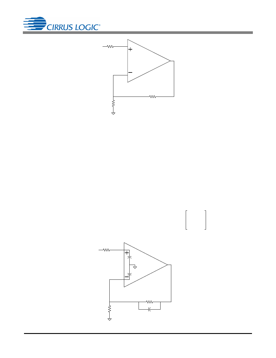
3.2 Open-loop Gain and Stability
3.2.1 Discussion
The CS3002 achieves ultra-high open-loop gain.
illustrates the amplifier in a non-inverting gain
configuration. The open-loop gain and phase plots
indicate that the amplifier is stable for closed-loop gains
less than 50V/V and R1
100
. For a gain of 50, the
phase margin is between 40
and 60 depending upon
the loading conditions. As shown in
, the operational amplifier has an input
capacitance at the + and – signal inputs of typically
50pF. This capacitance adds an additional pole in the
loop gain transfer function at a frequency defined using
Equation 1:
where
R = R1
R2; the parallel combination of R1 and R2
A higher value for R produces a pole at a lower
frequency, thus reducing the phase margin. Resistor R1
is recommended to be less than or equal to 100
,
which results in a pole at 30MHz or higher. If a higher
value of R1 is desired, compensation capacitor C2
should be added in parallel with resistor R2. Capacitor
C2 should be chosen using Equation 2:
The feedback capacitor C2 is required for closed-loop
gains greater than 50V/V. The capacitor introduces a
pole P
1
and a zero Z
1
in the loop gain transfer function
T(s), see Equation 3
f
1
2
R C
in
--------------------------
=
[Eq. 1]
R2 C2
R1 C
in
[Eq. 2]
R1
R2
Vin
Vo
R
S
CS3002
Figure 14. Non-inverting Gain Configuration
50 pF
50 pF
R1
R2
Vin
Vo
C2
C
in
C
in
Choose C2 so that R2
C2 R1 C
in
CS3002
Figure 15. Non-inverting Gain Configuration with Compensation
T s
1
s
Z
1
------
+
–
1
s
P
1
------
+
-------------------------
A
ol
=
[Eq. 3]