Transformer construction, 1 flyback transformer, 1 electrical specifications – Cirrus Logic CRD1615A-8W User Manual
Page 14
CRD1615A-8W
14
DS1043RD2
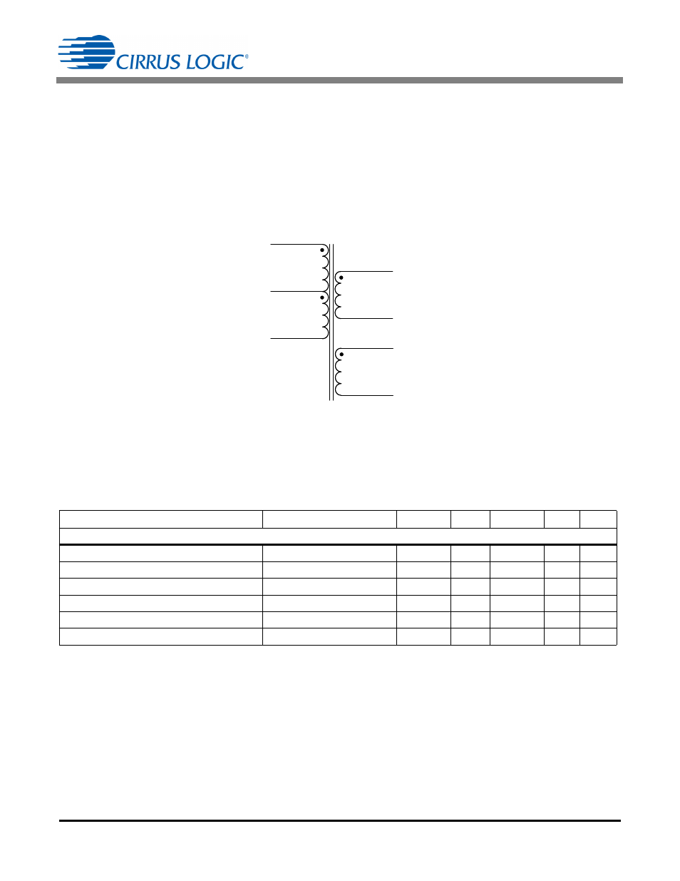
7. TRANSFORMER CONSTRUCTION
The CRD1615A-8W provides power factor correction and dimmer compatibility with a constant output current, quasi-
resonant flyback stage. The following sections describe the flyback transformer installed on the CRD1615A-8W.
7.1
Flyback Transformer
The flyback transformer stage is a quasi-resonant peak current-regulated DC-DC converter capable of delivering
the highest possible efficiency with constant current output while minimizing line frequency ripple. The auxiliary wind-
ing is used for zero-current detection and overvoltage protection.
7.1.1
Electrical Specifications
Characteristics conditions:
• Operating temperature range: -25 °C to +120 °C (including coil heat)
Notes:
1. Time = 2sec.
2. Measured across pins 4 and 5
3. Measured across pins B and A
4. Measured across pins 12 and 7
Parameter
Condition
Symbol
Min
Typ
Max
Unit
Flyback Transformer
Electrical Strength
(Note 1)
f
operate
=50/60Hz
-
3.75
-
kV
RMS
Primary Inductance
(Note 2)
f
resonant
=10kHz, 0.3V at 20°C
L
P
0.8
0.9
1.0
mH
Primary Leakage Inductance(Note 2)
f
resonant
=10kHz, 0.3V at 20°C
L
K
-
-
20
H
Primary DC Resistance
(Note 2)
t
DCR
=20°C
1.9
2.2
2.5
Secondary DC Resistance (Note 3)
t
DCR
=20°C
0.8
1.0
1.2
m
Auxiliary DC Resistance
(Note 4)
t
DCR
=20°C
3.0
3.5
4.0
m
48T
#27 AWG
(0.36 mm)
48 T
# 27AWG
(0.36mm)
48T
# 33AWG
(0.18mm)
Primary
4
6
5
12
Auxiliary
7
Secondary
(Triple Insulated )
48T
#30AWG
(0.255mm)
A
B
Figure 10. Flyback Transformer Schematic