Design process, 1 design considerations, An376 – Cirrus Logic AN376 User Manual
Page 2
AN376
2
AN376REV2
2. Design Process
Since the assumption is that the power factor is equal to 1 and the current obtained from the AC line is sinusoidal,
then the troughs of a rectified sinusoid line voltage deliver a current to the load that is also in a trough.
2.1 Design Considerations
The resulting current delivery to the LED load is equivalent to a [sin(
t)]
2
function. The squared sine is trans-
formed into a double angle equivalent using the trigonometric identity in Equation 1:
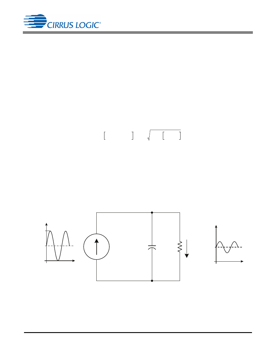
The power-reduction function is partitioned into two components: a DC component, and an AC component at
two times the line frequency. The amplitude of the AC component is equal to the amplitude of the DC component
(see Figure 2). Analysis indicates that a relationship exists between the RMS current and the DC current of the
output current I
OUT
. The RMS of the output current I
RMS
is calculated using Equation 2:
Equation 2 can be used to identify the DC portion, current I
DC
, of the output current, which is a sine wave with
a DC offset. Equation 3 defines the DC current to be approximately 82% of the RMS value of the output
current I
OUT
.
For the purpose of determining the ripple on the load current I
LED
flowing through the LEDs, only the AC com-
ponent is of interest. The AC component of the output current I
OUT
has an amplitude equal to the amplitude of
the DC current I
DC
and must be reduced by placing additional capacitance C
OUT
on the output of the converter.
t
2
sin
1
2
t
cos
–
2
----------------------------------
1
2
---
1
2
---
2
t
cos
–
=
=
[Eq. 1]
I
RMS
1
2
--- 1
2
---
2
t
cos
–
RMS
1
2
---
2
1
2
---
1
2
---
2
+
0.61
=
=
=
[Eq. 2]
I
DC
I
RMS
------------
0.5
0.61
-----------
0.82
=
=
[Eq. 3]
I
DC
t
I
DC
t
C
OUT
R
LED
I
LED
I
OUT
+
-
I
OUT
I
PK
I
LED
Figure 2. Model of LED Driver Output Circuit