Commissioning, operation, Connection diagram – WIKA A2G-20 User Manual
Page 10
WIKA operating instructions air2guide model A2G-20
GB
10
40339556.02 04/2012 GB/D/F/E/I
6. Commissioning, operation
Output 0 ... 10 V / 4 ... 20 mA (temperature)
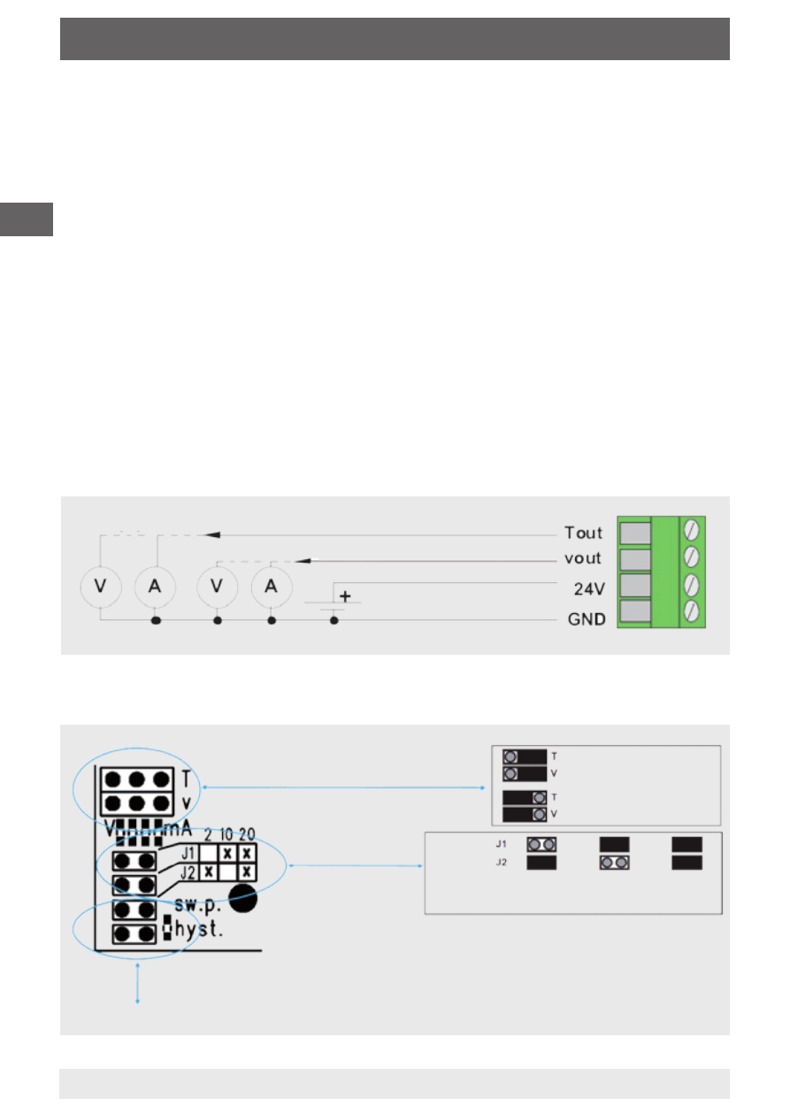
Connection diagram
Output 0 ... 10 V / 4 ... 20 mA (air velocity)
Supply voltage
Electrical connection
The instruments are designed to operate with safety extra-low voltage
(SELV). When wiring up the instruments, the technical specifications
for those instruments should be followed. In the case of a sensor with
transmitter, as a rule, the transmitter should be operated in the middle
of the measuring range, since deviations can occur at the range limits.
The ambient temperature of the transmitter electronics should be kept
constant.
The transmitters must be operated at a constant operating voltage
(±0.2 V). Current/voltage spikes from switching the power supply on or
off must be prevented by the customer.
Connection diagram
Temperature 4 ... 20 mA air
velocity 4 ... 20 mA
Temperature 0 ... 10 V air velocity
0 ... 10 V
see commissioning of the option with relay
Jumper:
Measuring range: 2 m/s
10 m/s
20 m/s
Jumper measuring range
Jumper for the setting of the outputs (mA/V)
Both outputs can be set independently