Commissioning, operation – WIKA LSO.25 User Manual
Page 23
WIKA operating instructions models LSO.06, LSO.25
23
13334603.01 09/2010 GB/D/F/E
6. Commissioning, operation
GB
The cable must not be shielded, however, should not be laid directly besides strong
electrical interference sources either. Including line resistance, contact resistance goes
the maximum line length and with that by the following table the maximum:
Wire cross section
in mm²
Wiring length
in m
Wiring resistance
in Ω
0.5
175
6.3
0.75
300
7.2
1.0
400
7.2
1.5
600
7.2
A complete resistance of 9 Ω, inclusive of contact resistances, should not be exceeded
since otherwise a failure signal is carried out.
In addition, for the explosion-protected version, a max. inductance of
L
a
≤ 0.5 mH and a max. capacitance of C
a
≤ 3 µF must be observed (incl.
switching amplifier values).
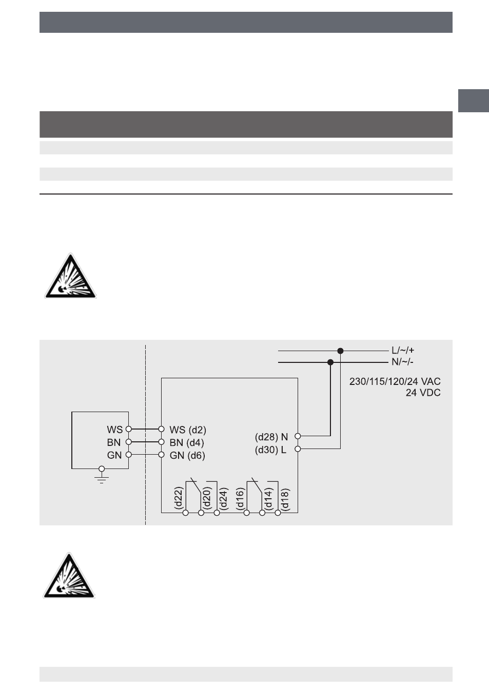
Connection diagram transducer and switching amplifier
For the explosion-protected version, a light-blue cable or one marked
light-blue must be installed from the switching amplifier to the transducer
(intrinsically safe circuit). The switching amplifier is located in the
non-hazardous area and the measuring body of the transducer in a Zone 1
area.
Ex zone 0/1
Safe area
Transducer
model LSO.06
Switching amplifier model LSO.25
Signal
Failure
The instrument can
be connected to
earth.