WIKA FLR User Manual
Page 7
GB
WIKA operating instructions level sensors model RMG
7
13442163.01 06/2010 GB/D/F
6.
Function test
6. Function test
A function test can only be carried out when the level sensor has been
removed.
■
Disconnect the cable
■
Connect an ohmmeter to two wires
■
Move the float by hand from Min. to Max.
■
The displayed resistance value changes continuously depending on
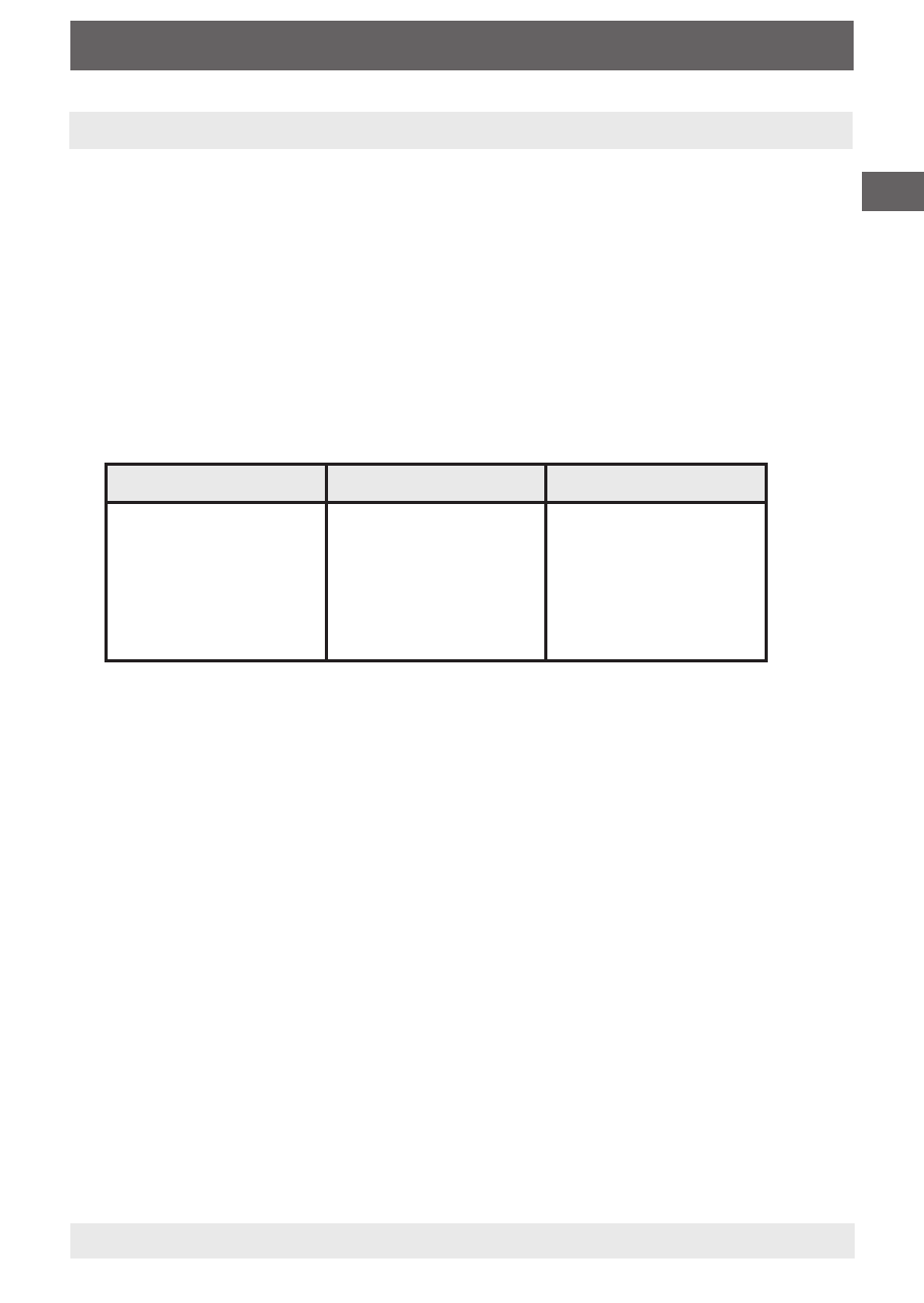
the connected wire colours (Tab. 1):
black-brown (R1)
blue-brown (R2)
black-blue (Ri)
Resistance value incre-
ases in proportion to
the height of the float.
Resistance value drops
from the value of the
total resistance inverse-
ly proportionally to the
height of the float.
Indication of the total
resistance (Ri)
Table 1
The value of the resistance chain is given on the tag plate mounted at
the level transmitter.
- 890.09.2190 (44 pages)
- A-10 (96 pages)
- A2G-50 (52 pages)
- A2G-55 (36 pages)
- AC-1 (88 pages)
- C-2 (24 pages)
- D-10-7 (112 pages)
- D-20-9 (35 pages)
- D-20-9 (51 pages)
- DG-10 (112 pages)
- DP-10 (44 pages)
- DPT-10 (92 pages)
- DPT-10 (96 pages)
- GCS-1 (76 pages)
- HP-2 (84 pages)
- IL-10 (31 pages)
- IPT-10 (36 pages)
- IPT-10 (56 pages)
- IPT-10 (48 pages)
- IPT-10 (28 pages)
- IS-20-F (7 pages)
- IS-20-F (43 pages)
- IS-20-H (7 pages)
- UT-10 (42 pages)
- UT-10 (52 pages)
- IUT-10 (78 pages)
- LH-10 (60 pages)
- LH-20 (60 pages)
- LS-10 (60 pages)
- MG-1 (92 pages)
- MH-1 (11 pages)
- MH-2 (9 pages)
- MHC-1 (84 pages)
- N-10 (35 pages)
- O-10 (108 pages)
- OT-1 (60 pages)
- P-30 (92 pages)
- PSA-31 (124 pages)
- PSD-30 (128 pages)
- R-1 (92 pages)
- S-10 (35 pages)
- S-11 (102 pages)
- S-20 (52 pages)
- S-20 (96 pages)
- SL-1 (21 pages)