Instruction manual ni-492e – WIKA TXA User Manual
Page 3
INSTRUCTION MANUAL
NI-492E
Rev. 0 01/05
6.1
PRELIMINARY OPERATIONS
Slide up the adjustment cover (Fig. 2, 1).
6.2
CALIBRATION CIRCUIT AND OPERATIONS
Prepare the control circuit as indicated in Fig.4.
The warning lamps should be connected to the terminals NA or
NC according to the required contact action.
Circuit C/NA
• This circuit closes with temperature on rise and opens with
temperature on fall when temperature reaches the set point.
Circuit C/NC
• This circuit opens with temperature on rise and closes with
temperature on fall when temperature reaches the set point.
The test instrument should have a measurement range
approximately equal to or slightly wider than the temperature
switch range and should have an accuracy consistent with the
precision required to calibrate the set point.
The temperature switch must be mounted in its normal
installation position, i.e. with the stem or capillary downwards.
Adjustments
Modify the temperature in the circuit up to the desired
microswitch set point value.
Turn the adjusting bush using the adjustment rod until the relative
lamp turns on (or turns off); then turn it in the opposite direction
until the lamp turns off (or on). Slowly turn the bush again until
the lamp turns on (or off).
If the instrument is equipped with two contacts, remember that
they are released simultaneously but within the specification
tolerance.
Fig. 4 -
Calibration circuit
TS - Temperature switch
TC - Test thermometer
VT - Thermostatic bath
6.3
FINAL OPERATIONS
Disconnect the instrument from the calibration circuit.
Close the adjustment slot by sliding down the slot cover (Fig. 2,
1), then seal with lead the instrument.
7 - INSTRUMENT PLUMBING
The plumbing (see Fig. 2), aimed as a guarantee against possible
tampering of the calibration, can be carried out using a flexible
steel wire (2), 1 mm
2
in section, wound up around the case in the
groove purposely provided.
8 - MOUNTING AND CONNECTIONS
8.1
NOUNTING
Mount instruments with capillary either on pipe or surface by
means of the proper bracket (see Fig. 8 and 9).
Select a location where possible shocks and temperature
variations remain within tolerable limits.
CAUTION: for instruments with capillary, the difference in height
between bulb and case is not to exceed two meters. If it does,
adjust set point temperature value according to the table given in
instruction IS-TC.401E.
For bracket mounting, see NI-292E.
8.2
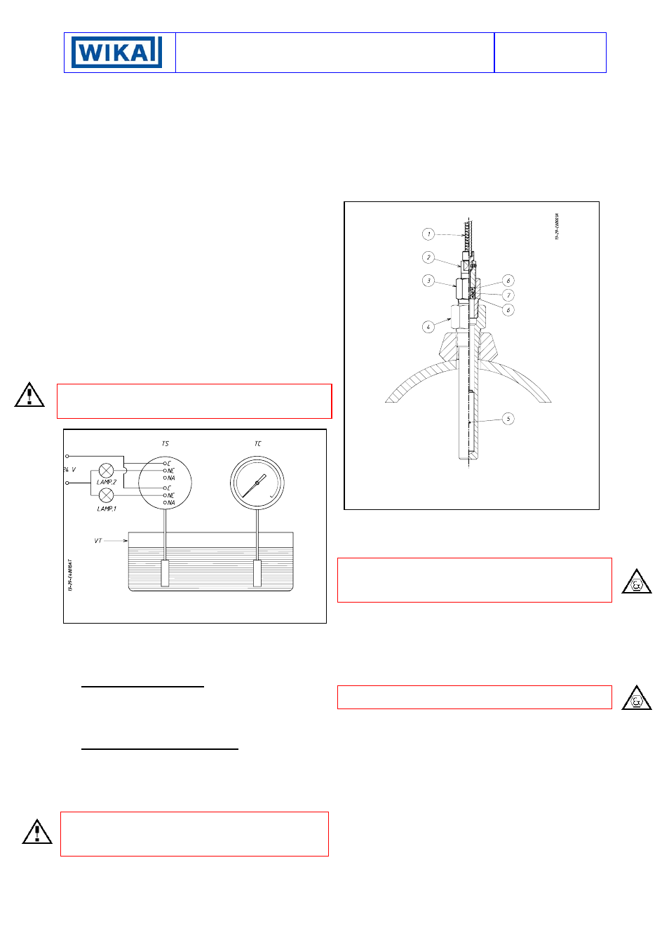
BULB AND CAPILLARY
With reference to Fig. 5, unscrew union (3) from stuffing gland
(2) and slide it out from bulb (5).
Mount union (3) on thermowell (4) and tighten it with a proper
wrench. Spread on bulb (5) the special paste for better heat
transmission and insert it into thermowell (4).
Be sure that bulb reaches thermowell bottom. Insert into union
(3) PTFE washer (7) with relevant st. st. washers (4). Screw
stuffing gland (2) into union (3) taking care not to twist capillary
and its armor, then tighten it until PTFE washer presses against
capillary.
Fig. 5 -
Bulb mounting
1) Armored
capillary
2) Stuffing gland (SW 12)
3) Union
4) Thermowell
5) Bulb
6) St. st. washer
7) PTFE
washer
Run armored capillary avoiding too narrow bends, then staple it.
Excess capillary, if any, is to be rolled up around a 200 mm dia.
min., then firmly secured.
8.3
ELECTRICAL CONNECTIONS
It is recommended to carry out the electrical connections
according to the applicable standards. In case of explosionproof
instruments (Series TXA) see also the Standards EN-60079-14
and EN-50281-1-2 .
The following mounting arrangements are possible.
8.3.1 MOUNTING WITH CABLE LOOSE (Fig. 10)
Run the cable so that it cannot be easily damaged (e.g. due to
too narrow bends, heat sources) and strain it.
Mount, if provided, the external ground device on the electrical
connection of the instrument. This device is to be threaded on,
while holding the electrical connection steady with a 27 mm
wrench on hex, until it reaches the bottom of the thread (Fig. 6).
The external ground screw is obligatory for explosionproof
constructions.