Instruction manual ni-492e – WIKA TXA User Manual
Page 2
INSTRUCTION MANUAL
NI-492E
R
EV
. 5 11/02
1 - GENERAL
1.1
FOREWORD
The wrong choice of a series or a model, as well as the incorrect
installation, lead to malfunction and reduce instrument life.
Failure to follow the indications given in this manual can cause
damage to the instrument, the environment and persons.
1.2
ALLOWED OVERRANGES
Temperatures exceeding the working range can be occasionally
tolerated provided they remain within the limits stated for the
instrument (proof temperature). Continuous temperatures
exceeding the working range can be applied to the instrument,
provided they are clearly stated in the instrument features.
The current and voltage values stated in the technical
specifications and data plate must not be exceeded: transitory
overranges can have a destructive effect on the switch.
1.3
TEMPERATURES
Due to the temperature of both the environment and the process
fluid, the temperature of the instrument could exceed the allowed
limits (normally from -40°C to +85°C). Therefore, in case it does,
suitable measures (protection against heat radiation, fluid
separators, cooling coils, heated lockers), aimed at limiting the
value, must be taken.
2 - OPERATING PRINCIPLE
The operating principle is based on a pressure measuring
element connected via a capillary tubing with a temperature
sensitive bulb. The system is partially filled with a volatile liquid
generating a pressure that is a non linear function of the bulb
temperature; this pressure is applied to a diaphragm acting on a
stiff disc with a force directly proportional to the bulb temperature.
The force is contrasted by an helical spring loaded by a suitable
bush. When the force balance point is exceeded, the stiff disc
shifts and, by means of a rigid rod, actuates one or two
simultaneous release electric microswitches. The
microswitches are of the snap acting type with automatic reset.
When the pressure moves away from the set values, returning
towards the normal values, the switch is reset.
3 - NAMEPLATE AND MARKINGS
The instrument is fitted with a metal plate bearing all its functional
characteristics and – in case of explosionproof execution (Series
TXA and TXN) – also the markings prescribed by standard EN
50014 and EN 50281-1-1. Fig. 1 shows the nameplate mounted
on explosionproof instruments.
Fig. 1 -
Nameplate, explosionproof instruments
1 CE marking and identification number of the notified body
responsible for production surveillance.
2 Apparatus classification according to ATEX 94/9 CE directive.
3 Notified body that issued the type certificate and number of said
certificate.
4 Mode of protection and operating ambient temperature limits.
4 - SPECIAL CONDITIONS FOR SAFE USE (X)
Explosionproof instruments (Series TXA and TXN) installed
without a junction box require an electric connection, suitable for
the mode of protection choosen, at the free end of the cable (see
Point 8).
5 - SET POINT ADJUSTMENT
The load of the helical spring can be adjusted by means of the
bush in such a way that the switch is released when the
temperature reaches (either increasing or decreasing) the desired
value (set point). The instrument is usually supplied with the
switches set at 0°C, or at the initial range value if this is above
0°C (factory calibration). The instrument is supplied with an
adhesive label showing the set point calibration value. With
factory calibration the values are not indicated on the label as
these are temporary and will be modified with the definitive
values. Prior to installation the instrument must be calibrated
and the definitive calibration values written on the label using a
suitable indelible ink pen.
If the instrument has been ordered with a specific calibration, it
is a good rule to check the calibration values marked on the
relevant adhesive label, prior to installation.
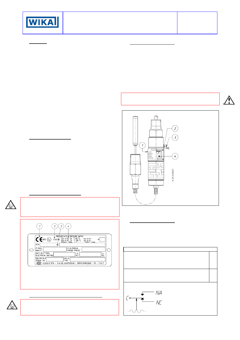
The position of the adjusting bush is given in Fig. 2.
Fig. 2 -
Adjusting bush and plumbing
c
Adjustment slot
cover
d
Stainless steel
wire
e
Sealing lead
f
Adjusting bush
The effect of the sense of rotation of the adjusting bush is shown
on the slot cover. Rotate the bush by inserting a 3mm dia. rod or
drill into the holes on the bush itself.
6 - SET POINT CALIBRATION
In order to proceed with the calibration and the periodical
functional verification of the instrument a suitable calibration
circuit (Fig. 4) and an adequate temperature source are
required.
Wiring is to be carried out as shown in Fig. 3 and on the slot
cover.
Fig. 3 -
Electric wiring
GDN - Ground internal : leadwire yellow/green
C - Common : leadwire brown
NA - Normally open : leadwire blue
NC - Normally closed : leadwire black
Micro 1
C - Common : leadwire grey
NA - Normally open : leadwire red
NC - Normally closed : leadwire white
Micro 2
Microswitch internal wiring. Contacts status with bulb at initial
range value.
C - Common
NA - Normally open
NC - Normally closed