Instruction manual ni-401e – WIKA TWG User Manual
Page 5
INSTRUCTION MANUAL
NI-401E
Rev. 3 07/99
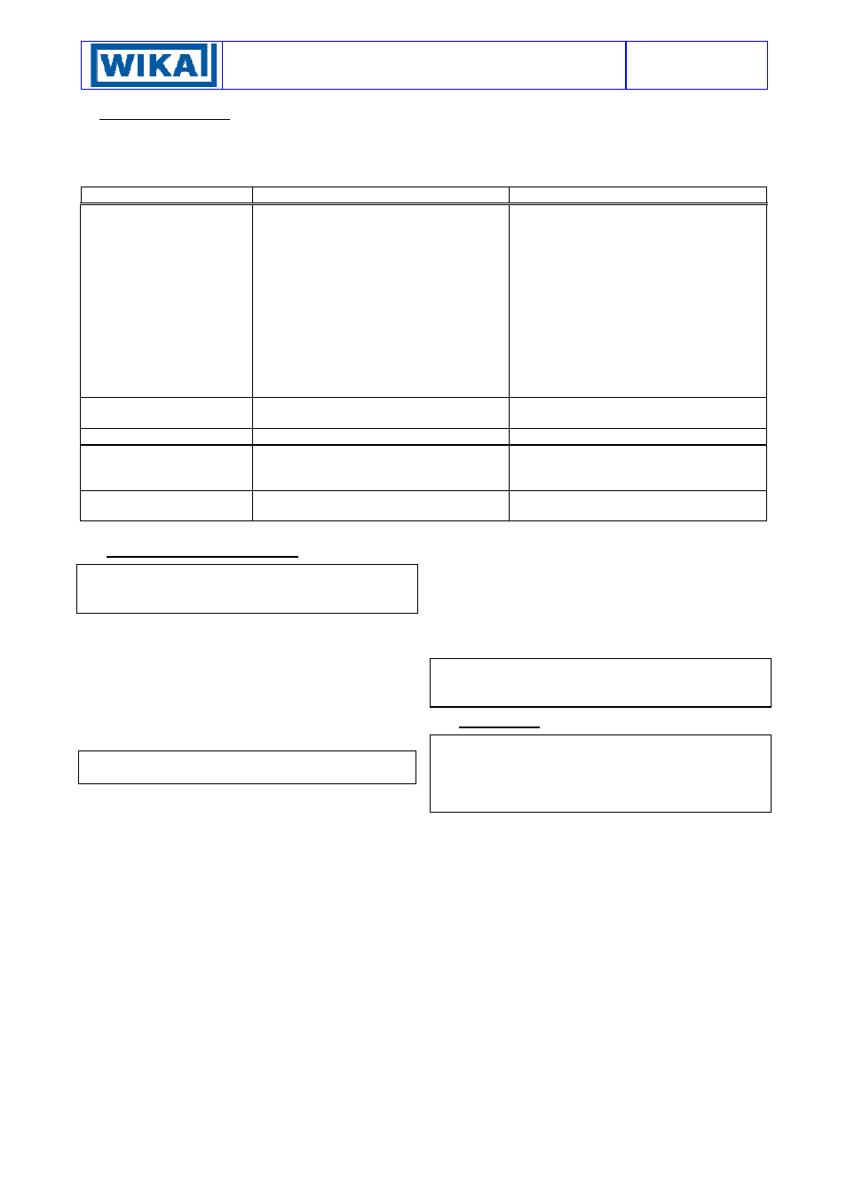
9 - TROUBLESHOOTING
IMPORTANT NOTE: operations involving replacement of essential components must be carried out at our
workshop, especially for instruments with explosionproof certificate; this is to guarantee the user the total and
correct restoration of the product’s original characteristics.
MALFUNCTION PROBABLE
CAUSE
REMEDY
Set point shift
Wear of contact surfaces between
microswitch pin and sensing element tip.
Wear of contact surfaces between
microswitch cradle and adjustment
screw.
Possible encrustations or corrosions on
above listed surfaces.
Permanent deformation of the sensitive
element due to fatigue or non-tolerated
over-ranges.
Loss of filling fluid.
Recalibrate
Recalibrate
Clean surfaces and recalibrate. Check
housing tightness.
Recalibrate or replace the sensitive
element with another made of a suitable
material. If necessary apply a fluid
separator.
Replace sensing element with another
one of same type
Poor Repeatability
Assembling screws loosened.
Check terminal screws, microswitch,
electrical subassembly, fastening screws
Slow Response
Encrustations on bulb or thermowell
Check and clean encrustated surfaces
Failed or Undue Actuation
Microswitch contacts damaged
Electrical joints loosened
Electrical line interrupted, or short circuit
Replace microswitch
Check all electrical joints
Check state of electrical line
Undue Actuation
Accidental impacts or excessive
mechanical vibrations
Modify installation arrangement
10 - STOPPING AND DISMOUNTING
Before proceeding with these operations ensure that the
plant or machines have been put into the conditions
foreseen to allow these operations.
10.1 Remove the power supply (signal) from the electrical
line.
With reference to figure 5.
10.2 Loosen and remove the stuffing nat (2) being careful
not to bend the capillary and protective sheath (1).
10.3 Loosen and remove the fitting (3) then extract the bulb
(5) from the thermowell (4) holding it by the capillary tube
(1), without bending it.
Do not waste in to environment the process fluid if
polluting or harmful to people.
With reference to figures 6 and 7.
10.4 Unscrew the three piece joint (8) (electrical cable
tubing).
10.5 Remove the instrument cover and disconnect the
electrical cables from the terminal block and earth screws.
10.6 Remove the screws fixing the case to the panel (or
pipe) and remove the instrument, taking care to slide the
electrical conductors out from the case.
Replace the instrument cover. Insulate and protect the
conductors remaining on the plant. Temporarily plug the
thermowell.
11 - DEMOLITION
The instruments are mainly made of stainless steel and
aluminium and therefore, once the electrical parts have
been dismounted and the parts coming into contact with
fluids which could be harmful to people or the environment
have been properly dealt with, can be scrapped.