Instruction manual ni-401e – WIKA TWG User Manual
Page 2
INSTRUCTION MANUAL
NI-401E
Rev. 3 07/99
1 - GENERAL NOTES
1.1 FOREWORD
The wrong choice of a series or a model, as well as the
incorrect installation, lead to malfunction and reduce
instrument life. Failure to follow the indications given in this
manual can cause damage to the instrument, the
environment and persons.
1.2 ALLOWED OVERRANGE
Temperatures exceeding the working range can be
occasionally tolerated provided they remain within the
limits stated in the instrument features (vacuum or proof
temperature). Continuous temperatures exceeding the
working range can be applied to the instrument, provided
they are clearly stated in the instrument features. The
current and voltage values stated in the technical
specifications and ratings must not be exceeded.
Transitory overranges can have a destructive effect on the
switch.
1.3 MECHANICAL VIBRATIONS
Can generally lead to the wearing of some parts of the
instrument or cause false actuation. It is therefore
recommended that the instrument be installed in a place
where there are no vibrations. In cases where this is
impossible it is advisable to take measures to lessen the
effects (elastic supports, installation with the pin of the
microswitch positioned at right angles to the vibration
plane, etc.).
1.4 TEMPERATURE
Due to the temperature of both the environment and the
process fluid, the temperature of the instrument could
exceed the allowed limits (normally from -20° to +70°C).
Therefore, in case it does, suitable measures (protection
against heat radiation, heated cabinets) must be taken.
2 - OPERATING PRINCIPLE
The thermometric bulb is constituted by a rigid constant-
volume container. It is connected via capillary tubing to a
pressure measuring element (bourdon tube). This system
is filled with gas, and its absolute pressure is proportional
to absolute temperature (Charles’ law). As a consequence,
any change in bulb temperature causes a change in gas
pressure acting on sensible element, causing its free tip to
undergo an elastic deflection which is used to actuate one
or two electrical microswitches adjusted at prefixed set
point values.
3 - SET POINT REGULATION
3.1 Each microswitch is independent and can be
regulated by means of a screw (for adjustment) in such a
way that it actuates when the temperature reaches
(increasing or decreasing) the desired value (set point).
3.2 The instrument is usually supplied with the switches
set at 0°C or at the lowest setting range value if this is
higher than 0°C (factory calibration).
3.3 The instrument is supplied with an adhesive label
showing the set point calibration value. With factory
calibration the values are not indicated on the label, as
these are temporary and will be modified with the definitive
values.
3.4 Prior to installation the instrument must be calibrated
and the definitive calibration values written on the
adhesive label using a suitable indelible ink pen.
3.5 If the instrument has been expressly ordered with
specific calibration, it is a good rule to check the
calibration values stated on the adhesive label, prior to
installation.
3.6 The position of the adjustment screws is given in fig. 1.
3.7 The effect that the direction of rotation of the
adjustment screws is described on the adhesive label.
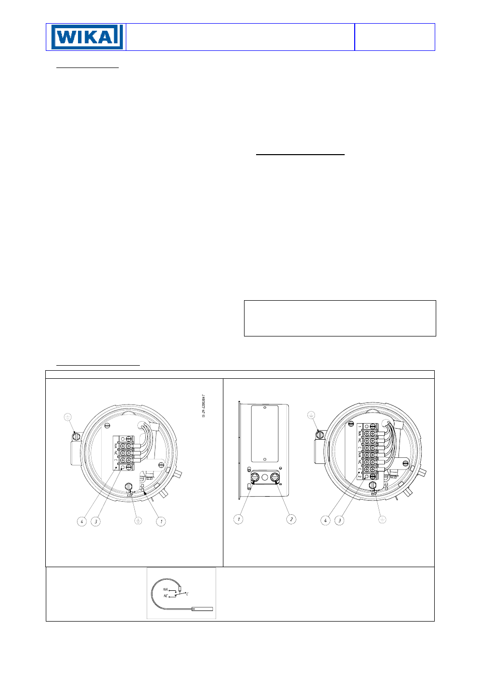
fig. 1 - Electrical connections and adjustment screws
One contact instruments
Two contact instruments
1 - Microswitch set point calibration screw
3 - Terminal block
4 - Electrical connection identification plate
1 – Microswitch 2 set point calibration screw
2 – Microswitch 1 set point calibration screw
3 – Terminal block
4 – Electrical connection identification plate
Designation of the contacts:
C - Common
NA - Normally Open
NC - Normally Closed
Microswitch electrical circuit: State of the contacts at initial temperature
range (when factory calibrated)