Instruction manual ni-401e – WIKA TWG User Manual
Page 3
INSTRUCTION MANUAL
NI-401E
Rev. 3 07/99
4 - SET POINT CALIBRATION
In order to proceed with the calibration and the periodical
functional verification of the instrument a suitable
calibration circuit (fig. 3) and an adequate heat source is
required.
4.1 PRELIMINARY OPERATIONS
4.1.1
Weatherproof temperature switches (Series
TWG) (Fig. 2)
Remove the blocking device fixed to the side of the
instrument case and the adjustment screw access plate.
Remove the cover be rotating it anticlockwise.
fig.
2
-
Weatherproof tempeature switch cover blocking
device and plumbing
a) Plumbing
wire
b) Plumbing
c) Blocking
nut
d) Blocking
bracket
e) Adjustment screws access plate
4.1.2
Explosionproof temperature switches (Series
TAG) (Fig. 3)
Loosen the locking headless screw situated on the cover
using a 1,5 hexagonal key then unscrew the cover.
Remove the internal blocking device inserted on the
closure plugs and slide out the plugs.
fig. 3 - Explosionproof temperature switch cover blocking
device
4.1.3
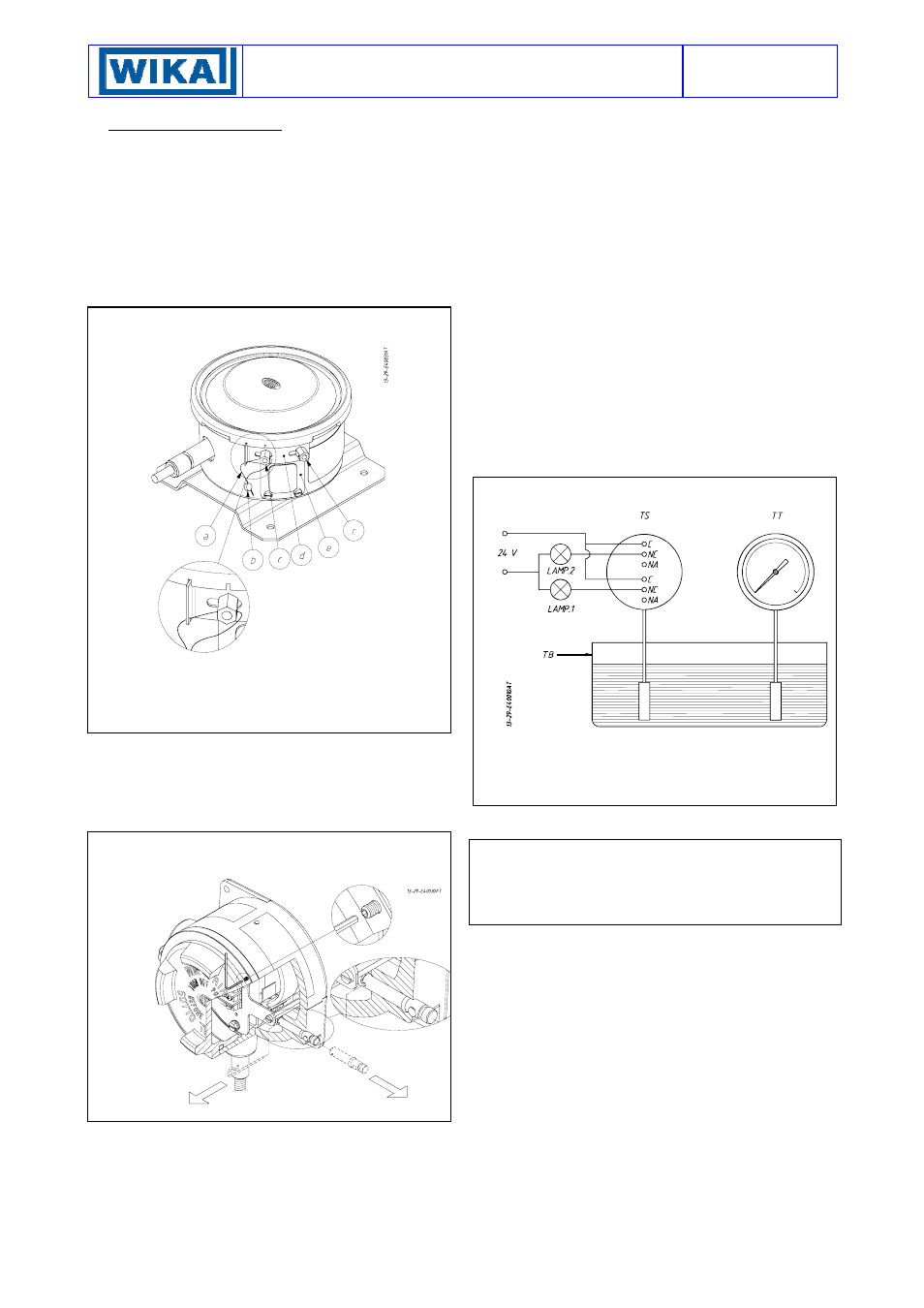
4.2 CALIBRATION CIRCUIT AND OPERATIONS
4.2.1 Prepare the control circuit as indicated in Fig. 4.
4.2.2 The warning lamps should be connected to contact 1
or 2 in the NO or NC position according to the required
contact action.
Connection of C and NO terminals
• If the circuit is open at the working temperature, the
switch closes the circuit as the temperature increases
when the desired value is reached.
• If the circuit is closed at the working temperature, the
switch opens the circuit as the temperature decreases
when the desired value is reached.
Connection of C and NC terminals
• If the circuit is closed at the working temperature, the
switch opens the circuit as the temperature increases
when the desired value is reached.
• If the circuit is open at the working temperature, the
switch closes the circuit as the temperature decreases
when the desired value is reached.
4.2.3 The test instrument should have a measurement
range approximately equal to or slightly wider than the
temperature switch range and should have an accuracy
consistent with the precision required to calibrate the set
point.
4.2.4 The temperature switch must be mounted in the
normal installation position, i.e. with the stem or capillary
outlet downwards.
fig. 4 - Calibration circuit
TS -
Temperature switch
TT -
Test thermometer
TB -
Thermostatic bath
4.2.5 Avoid forcing the microswitch by hand or with tools.
This could affect the instrument functioning.
CAUTION: If the switch is of the kind with adjustable dead
band (letter R in the contact codes) before proceeding with
the following operations (4.2.6-4.2.11) it is necessary to
proceed with the adjustment of the differential (see
attachment NI-705).
4.2.6 Increase the temperature in the circuit up to the
desired set point value for the first microswitch.
4.2.7 Use a wide bladed screwdriver, as indicated on the
adhesive label, until the relative lamp turns on (or turns
off).
- If the instrument is equipped with only one contact the
calibration is complete.
- If it is equipped with two contacts continue in the
following manner.
4.2.8 Vary the temperature until the desired set point value
for the second microswitch is reached.
4.2.9 Act on the adjustment screw of the second contact
as in point 4.2.7.
4.2.10 Repeat operations 4.2.6 and 4.2.7 on the first
contact, then operations 4.2.8 and 4.2.9 on the second
contact, until the required set point precision is obtained.
This is necessary due to the reciprocal influence which the
microswitches have with the sensitive element of the
instrument.