Instruction manual ni-401e – WIKA TWG User Manual
Page 4
INSTRUCTION MANUAL
NI-401E
Rev. 3 07/99
4.2.11
Check the calibration values (varying the
temperature in the circuit accordingly) and record them on
the adhesive label using a pen with indelible ink.
4.3 FINAL OPERATIONS
4.3.1 Disconnect the instrument from the calibration circuit.
4.3.2
Weatherproof temperature switches (Series
TWG)
Take the cover, ensure that the sealing gasket is correctly
fitted into its seat, insert the cover onto the case, with the
blocking gap positioned in correspondence to the blocking
bracket.
Turn the cover clockwise closing it tightly.
Mount the adjustment screws access plate, then the
blocking device as in figure 2.
4.3.3
Explosionproof temperature switches (Series
TAG)
Insert the closure plugs of the adjustment screw access
holes, block them using the internal device and if
necessary seal them with plumbing. Screw on the cover
and block it using the headless screw with which it is
equipped (Fig. 3).
4.3.4 Replace the supplied protection cap on the cable
conduit.
IMPORTANT: the protection cap should only be
definitively removed during the connection steps (see §5)
5 - MOUNTING AND CONNECTIONS
5.1 MOUNTING
Surface mount the instrument by means of the holes
provided, or pipe mount using the appropriate bracket
(see figures 6 and 7) in a vertical position (with the stem or
capillary outlet downwards). The chosen position must be
such that vibrations, accidental shocks or temperature
changes are within tolerable limits. The above also applies
to direct mounting.
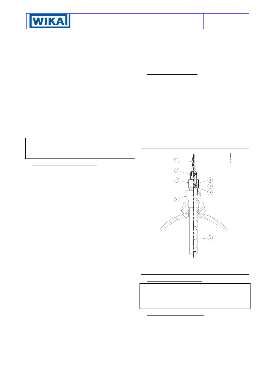
5.2 BULB AND CAPILLARY
With reference to figure 5 unscrew the fitting (3) from the
seal press (2) and slide it off from the bulb (5). Mount the
fitting (3) on the thermowell and tighten it using the
appropriate key. Insert the bulb (5) into the thermowell (4)
after covering it with the paste to improve the transmission
of heat. Verify that the bulb touches the bottom. Insert the
PTFE seal with the relative stainless steel washers into the
fitting (3). Screw the seal press (2) onto the fitting (3)
taking care not to bend the capillary and relative sheath
and tighten until the PTFE seal is tight on the capillary
tube. Run the capillary protected by the armor in the
established direction, avoiding tight bends, and block
using the stainless steel bands. If a large amount of
capillary remains this should be rolled up and fixed tightly.
The coil must not have a diameter of less than 200 mm.
5.3 ELECTRICAL CONNECTIONS
5.3.1 Set up the cable protection tube according to the
applicable standards (especially for explosion-proof
prescriptions). In many applications this is associated to
the process piping and is subject to condensation. For this
reason it is necessary to provide means to prevent
condensation from entering the instrument case. The
arrangement shown in figure 6 or 7 is therefore
recommended.
5.3.2 Check that there is no power in the lines.
5.3.3 Remove the cover and carry out the cabling and
connections to the terminal block (see fig. 1).
Flexible cables with a maximum section of 1.2 mm
2
(16AWG) are recommended using pre-insulated fork
thimbles. Do not touch the adjustment screws and do
not bend the elastic microswitch supports in order to
prevent the instrument calibration being altered.
5.3.4 Ensure that no deposits or wire ends remain inside
the case.
5.3.5
Once the connection operations have been
completed, replace the cover and ensure that it is properly
sealed and blocked. See Fig. 2 and 3.
6 - INSTRUMENT PLUMBING
6.1
Weatherproof temperatures switches (Series
TWG)
The plumbing, aimed as a guarantee against possible
tampering of the calibration and electrical connections, can
be carried out using a flexible steel wire (a) inserted into
the holes in the locking nut (c) and the bracket (d)
provided for this purpose (see figure 2).
6.2
Explosionproof temperature switches (Series
TAG)
Plumbing is not necessary as the cover is blocked with a
headless screw, the closure plugs of the adjustment screw
access holes are blocked by means of the internal
blocking device and the instrument does not have to be
opened when installed.
fig. 5 - Mounting the bulb
1) Armored
capillary
2) Stuffing nut (SW 12)
3) Rotating fitting (SW 22)
4) Thermowell
5) Bulb
6)
Stainless steel washer
7) PTFE
washer
7 - PUTTING INTO OPERATION
As the signal transmitted by the instrument is used in a
complex system, it is necessary that the means of putting
it into operation are established by those in charge of the
plant. The instrument starts working as soon as it is
connected to an electrical line.
8 - FUNCTIONAL VERIFICATION
This will be carried out according to the Client’s control
procedures. Series TWG instruments can be verified.
Series TAG instruments can only be verified on the plant if
test equipment suitable for the environment is available
and if there is no current in the electric line.
If this is not the case it is necessary to stop operation,
dismount by means of the three piece joints and carry out
the verification in a test room. Verification consists in
checking the calibration value and possibly regulatory
the adjustment bush (see §4).