Instruction manual ni-223e, Caution – WIKA DE User Manual
Page 5
INSTRUCTION MANUAL
NI-223E
Rev. 2 11/02
CAUTION:
fittings used for the electrical connection of the
pressure switch Series DE (explosionproof) shall be certified to
Standards EN 50014 and 50018, and shall guarantee instrument
degree of protection (IP65).
Check that there is no power in the lines.
Remove the cover and carry out the cabling and connections to
the terminal block (see fig.2). Flexible cables with a maximum
section of 1,2 mm
2
(16AWG) are recommended using the pre-
insulated thimbles with a maximum diameter of 2,5 mm supplied
with the instrument.
When inserting cables into the enclosure pay attention not to
force the microawitch with cable or tools, otherwise instrument
calibration or even its operation could be compromised. The mi-
croswitch has been factory mounted and positioned in order to
obtain the best performances. Any tampering made on site with-
out following instructions authorised by the E. CELLA SPA may
result in instrument malfunction.
Ensure that no deposits or wire ends remain inside the case.
Once the connection operations have been completed, replace
the cover and ensure that it is properly sealed and blocked (see
fig. 3).
7.4
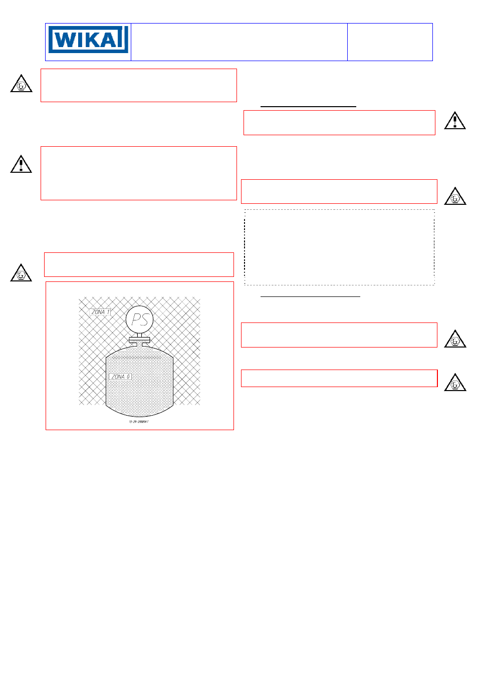
SPECIAL NOTE FOR INSTALLATION OF
CATEGORY 1 / 2 G PRESSURE SWITCHES
Explosionproof pressure switches (Series DE) can be installed on
processes requiring apparatus of group II category 1 in an ambi-
ent requiring apparatus of group II category 2 (see Fig. 5).
Fig. 5 -
Installation of Group II Cat. 1 / 2 G instruments
8 - PUTTING INTO OPERATION
As the signal transmitted by the instrument is used in a complex
system, it is necessary that the means of putting it into operation
are established by personnel in charge of the plant
.
The instrument comes into operation as soon as the root valves
are opened and then, afterwards, the service valve attached to
the instrument + inlet pipe is opened, the by-pass valve closed
and the service valve attached to the instrument - inlet pipe is
opened. Any possible drainage of the connection tubing can be
carried out by opening the drains fitted the instrument.
In case of explosionproof instruments (Series DE), initial inspec-
tions are to be carried out according to customer procedures and
at least in accordance with Standard EN-60079-17.
NOTE: : if the instrument is used for level control in tanks under
pressure and is installed according to the diagram in fig.9 pro-
ceed as follows. Close the root valves V
1
and V
2
open the valves
V
3
V
4
V
5
(the service and by-pass valves). Fill with the process
fluid, from plug S
B
positioned on the seal pot B, bleeding air from
the plug S positioned on the seal pot near the V
2
valve. Then
close S and top up the liquid in B. Remove air from the breather
plug S
+
and S
-
positioned on the instrument, topping up the liquid
in B. Close the plug S
B
and the by-pass valve V
5
and open the
root valves V
1
and V
2
. The instrument is ready for use.
9 - FUNCTIONAL VERIFICATION
This will be carried out according to the Client’s control proce-
dures. Series DC instruments can be verified on the plant if in-
stalled as illustrated in fig.6 or 7.
The instruments Series DE may be checked on site only if
apparatus suitable for explosive atmosphere are used and
provided that the electric line is not energized
If this is not the case it is necessary to stop operation, dismount
by means of the three piece joints and carry out the verification in
a test room.
CAUTION: do not open the cover of explosionproof pressure
switches (Series DE) when energized, in explosive atmospheres.
Verification consists in checking the calibration value and pos-
sibly regulating the adjustment screw (see par.5).
In case of explosionproof instruments (Series DA), inspections of
the electrical installation are to be carried out also according to
customer procedures and at least in accordance with Standard
EN-60079-17.