Instruction manual ni-223e – WIKA DE User Manual
Page 3
INSTRUCTION MANUAL
NI-223E
Rev. 2 11/02
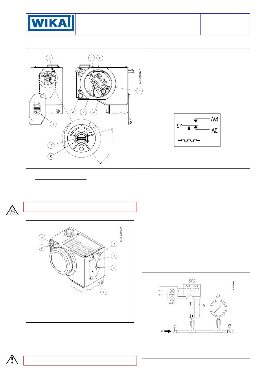
Fig. 2 -
Electrical connections and adjustament screws with one or two contacts instruments
1 - Adjustment screw
2 - Screw for fixing the adjustement
3 - Terminal block for the first microswitch
4 - Hole for test plug
5 - Terminal block for the first microswitch
6 - Internal earth screw
7 - Pre-insulated thimbles
8 - External earth screw
9 - Adjustment bush access plate
10 - Graduated dial
Microswitch electrical circuit.
State of the contacts at atmospheric pressure
Designation of the contacts:
C – Common
NA – Normaly open
NC – Normaly closed
5 - SET POINT CALIBRATION
In order to proceed with the calibration and the periodical func-
tional verification of the instrument a suitable calibration circuit
(fig.4) and an adequate pressure source is required.
5.1 PRELIMINARY OPERATIONS
CAUTION: do not open the cover of explosionproof pressure
switches (Series DE) when energized, in explosive atmospheres.
With reference to fig.3 unscrew the screw (b) until the blocking
device (a) can be turned 180°; then unscrew the cover.
Fig. 3 -
Cover blocking device and plumbing
a - Cover blocking device
b - Blocking screw
c - Screw blocking the adjustment bush access plate
d - Flexible steel wire
e - Plumbing
f - Adjustment bush access plate
5.2 CALIBRATION CIRCUIT AND OPERATIONS
Prepare the control circuit as indicated in Fig. 3 by connecting the
+ (or H) port to the pressure source and leaving the - (or L) port
open to the atmosphere.
The warning lamps should be connected to the contacts in the
NA or NC (NA = Normally Open NC = Normally Closed) position
according to the required contact action.
If the instrument is equipped with two microswitches, take into
account that they actuate simultaneously within rated tolerances.
The warning lamps can either be connected by means of a thim-
ble with a maximum diameter of 2.5 mm or by means of a test
plug with a diameter of 2 mm to be inserted in the appropriate
holes situated frontally beside the terminal screw (see fig.2).
Connection of C and NO terminals
• If the circuit is open at the working pressure, the switch closes
the circuit as the pressure increases when the desired values is
reached (MAKE on Raise).
• If the circuit is closed at the working pressure, the switch opens
the circuit as the pressure decreases when the desired value is
reached (BREAK on Fall).
Connection of C and NC terminals
• If the circuit is closed at the working pressure, the switch opens
the circuit as the pressure increases when the desired value is
reached (BREAK on Raise).
• If the circuit is open at the working pressure, the switch closes
the circuit as the pressure decreases when the desired value is
reached (MAKE on Fall).
The test instrument should have a measurement range approxi-
mately equal to or slightly wider than the differential pressure
switch range and should have an accuracy consistent with the
precision required to calibrate the set point.
The differential pressure switch must be mounted in the normal
installation position, i.e. with the pressure connections down-
wards.
Fig. 4 -
Calibration circuit
DPS Differential pressure switches
Test fluid:
CA
Test gauge
air for
P
≤ 10 bar
V1
Inlet valve
water for P > 10 bar
V2 Discharge
valve
P Pressure
source
Avoid forcing the microswitch by hand or with tools. This could af-
fect the instrument functioning.
With reference to fig.3, clear the access to the adjustment bush
by loosening the screw (c) which holds the access plate (f).
≅ 5% span