Instruction manual ni-223e – WIKA DE User Manual
Page 2
INSTRUCTION MANUAL
NI-223E
Rev. 2 11/02
1 - GENERAL NOTES
1.1 FOREWORD
The wrong choice of a series or a model, as well as the incorrect
installation, lead to malfunction and reduce instrument life. Fail-
ure to follow the indications given in this manual can cause dam-
age to the instrument, the environment and persons.
1.2 ALLOWED OVERRANGE
Differential pressure exceeding the working range can be occa-
sionally tolerated provided they remain within the limits stated in
the instrument features (vacuum or proof pressure). Continuous
differential pressure exceeding the working range can be applied
to the instrument, provided they are clearly stated in the instru-
ment features. The current and voltage values stated in the tech-
nical specifications and ratings must not be exceeded. Transitory
over-ranges can have a destructive effect on the switch.
1.3 MECHANICAL VIBRATIONS
Can generally lead to the wearing of some parts of the instrument
or cause false actuation. It is therefore recommended that the in-
strument be installed in a place where there are no vibrations. In
cases where this is impossible it is advisable to take measures to
lessen the effects (elastic supports, installation with the pin of the
microswitch positioned at right angles to the vibration plane, etc.).
1.4 TEMPERATURE
Due to the temperature of both the environment and the process
fluid, the temperature of the instrument could exceed the allowed
limits (normally from -40° to +60°C). Therefore, in case it does,
suitable measures (protection against heat radiation, fluid separa-
tors, cooling coils, heated lockers) must be taken. The process
fluid or its impurities must not in any case solidify inside the in-
strument chambers.
2 - OPERATING PRINCIPLE
The differential pressure, acting on the sensitive diaphragm ele-
ment, determines its elastic deformation which is used to actuate
one or two simultaneous release electric microswitches. The
microswitches are of the snap acting type with automatic reset.
When the pressure moves away from the set values, returning
towards the normal values, the switch is reset.
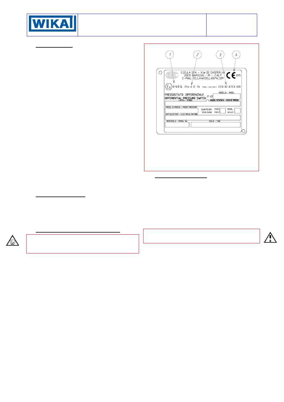
3 - IDENTIFICATION PLATE AND MARKINGS
The instrument is fitted with a metal plate bearing all its functional
characteristics and – in case of explosionproof execution (Series
DE) – also the markings prescribed by standard CEI EN 50014.
Fig. 1 shows the plate mounted on explosionproof instruments.
Fig. 1 -
Explosionproof instruments plate
1
CE marking and identification number of the notified body
responsible for production surveillance.
2
Apparatus classification according to ATEX 94/9 CE direc-
tive.
3
Type of protection and ambient temperature limits of opera-
tion.
4 Notified body that issued the type certificate and number of
said certificate.
4 - SET POINT REGULATION
Adjustment is made by turning a screw that makes the
switch/switches activate when the pressure (increasing or de-
creasing) reaches the desired value (set point). The instrument is
usually supplied with the switches set at the setting range value
nearest to zero (factory calibration). The instrument is supplied
with an adhesive rating plate showing the set point calibration
value. With factory calibration the values are not indicated on
the ratings as these are temporary and will be modified with the
definitive values. Prior to installation the instrument must be cali-
brated and the definitive calibration values written on the adhe-
sive rating plate using a suitable indelible ink pen.
If the instrument has been ordered with a specific calibration, it
is a good rule to check the calibration values marked on the
relevant adhesive label, prior to installation.
The adjustment screw (fig.2) , which acts on the switch, is part of
the transmission system for shifting the sensor element. The ad-
justment must therefore be made very carefully. To facilitate the
calibration operation (§ 5.2) , its seat is provided with a graduated
scale; each increment of this scale equals approximately 5% of
the full range of the differential pressure switch. Therefore, using
the slot on the top of the adjustment screw as a reference, the
screw can be turned to obtain a certain value.
The effect that the direction of rotation of the adjustment screws
has is described on the adhesive plate.