Instruction manual ni-223e – WIKA DE User Manual
Page 4
INSTRUCTION MANUAL
NI-223E
Rev. 2 11/02
Increase gradually pressure in the circuit up to the desired mi-
croswitch set point value (P
i
).
If the switch activates during the aforesaid operation, turn the ad-
justment screw in the + direction until the switch activates again.
If it does not activate, rotate the adjustment screw in the - direc-
tion until the switch activates.
Raise the circuit pressure to the normal working value.
Slowly return to the intervention pressure until the indicator lamp
turns on (or off), and note the pressure value (P
r
).
Calculate the difference between the set and noted pressure val-
ues (P
i
–
P
r
= D).
Calculate what percent the difference D is of the full differential
pressure range.
Annul the pressure difference, D, by turning the adjustment screw
the appropriate amount and in the appropriate direction, using the
graduated scale as a reference (§ 4 and fig.2).
Check the pressure calibration value by appropriately varying the
circuit pressure. Note this value on the adhesive label using an
indelible ink pen.
Example: Instrument with 0-1 bar range.
Desired set point value:
400 mbar
Read set point:
415 mbar
Difference:
D = 400-415 = - 15 mbar
Correction: Turn the adjustment screw in the pressure-reducing
direction a distance equal to 1/3 of the full-scale reading of the
graduated scale.
5.3 FINAL OPERATIONS
Disconnect the instrument from the calibration circuit.
With reference to fig.2 close the access to the adjustment bush
by rotating the access plate (9) and tighten the relative screw (2).
Take the cover, ensure that the sealing gasket is correctly fitted
into its seat, insert the cover onto the case and turn it clockwise
until the cover is closed. With reference to fig.3 turn the blocking
device (a) 180° sliding the tongue into the appropriate seat in the
cover; then tighten the blocking screw (b).
Mount on pressure connections and cable entry the protection
caps supplied with the instrument. The protection caps should
only be definitively removed during the connection steps (see §
7).
6 - INSTRUMENT PLUMBING
With reference to fig. 3 the plumbing, aimed as a guarantee
against possible tampering of the calibration, can be carried out
using a flexible steel wire (d) inserted into the holes in the screw
(c) and the adjustment bush access plate (f) provided for this
purpose.
7 - MOUNTING AND CONNECTIONS
7.1 MOUNTING
Surface mount the instrument by means of the holes provided, or
pipe mount using the appropriate bracket (see fig.8). The chosen
position must be such that vibrations, the possibility of shocks or
temperature changes are within tolerable limits. With gas or va-
pour process fluid, the instrument must be positioned higher than
the pipe inlet (see fig. 7). With a liquid process fluid, the instru-
ment can be positioned higher or lower, indifferently (see fig.6
and 7).
7.2 PRESSURE CONNECTIONS
Connecting lines are an integral part of the instrument in trans-
mitting the measured variable from the measuring point to the in-
strument.
For a correct installation it is necessary to:
Mount a shut-off valve with drain (root valve) on each process
pipe inlet to allow the instrument to be excluded and the connec-
tion tubing to be drained. It is recommended that said valve has a
capstan blocking device aimed at preventing it being activated
casually and without authorisation.
Mount a 3 valve manifold near the instrument to permit possible
functional verification on site and removal of the instrument. It is
recommended that the manifold is made up of two service valves,
one by-pass valve and two suitably connected drain plugs.
Mount a three piece joint onto the threaded connections of the in-
strument to permit the easy mounting or removal of the instru-
ment itself.
Carry out the connection using a flexible tube in such a way that
variations in the temperature of the tube itself do not force the in-
strument connections.
Ensure that all the pressure connections are airtight. It is impor-
tant that there are no leakage in the circuit.
Close root valves, the two service valves, drain plugs and open
the by-pass valve.
NOTE: if the instrument is used for level control in tanks under
pressure it is recommended that installation is carried out accord-
ing to the diagram in fig.9; ensuring that
• the distance K is greater than 0,5 m
• the seal pot B has a sufficient capacity to maintain the liquid
level at the maximum height over time.
7.3 ELECTRICAL CONNECTIONS
It is recommended to carry out the electrical connections accord-
ing to the applicable standards. In case of explosionproof instru-
ments (Series DE) see also the Standard EN-60079-14. If the
electrical connection is carried out in a protected tube, it shall be
made so that condensate is prevented from entering instrument
enclosure.
The arrangement shown in
fig. 6 or 7
is therefore recommended.
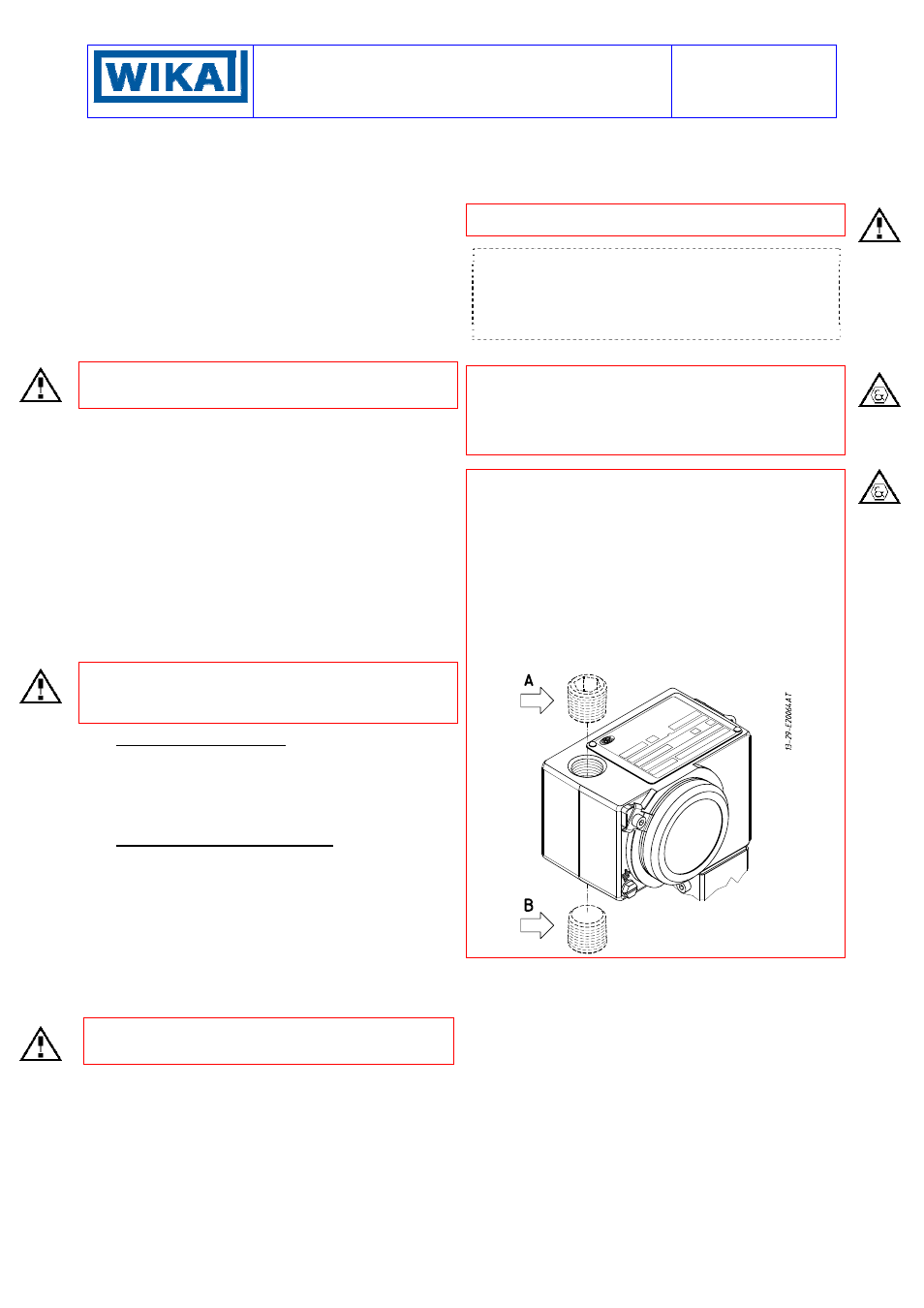
WARNING: the cable entry not used must be plugged and
sealed using the plug supplied with the instrument, in order to
prevent rain water or other liquids from entering the enclosure.
Should the enclosure be explosionproof the EEx-d degree of pro-
tection is NOT guaranteed unless the plug is correctly mounted
and blocked in such a way that it cannot be removed. Further-
more, in order to guarantee the degree of protection IP65 and
the unlocking of the blocking joint or cable gland from the enclo-
sure, the coupling thread must be sealed with the same anaero-
bic sealing used for the plug on the unused cable entry (e.g.: Loc-
tite ® 648)