Instruction manual ni-209e – WIKA DA10 User Manual
Page 6
INSTRUCTION MANUAL
NI-209E
Rev. 4 12/02
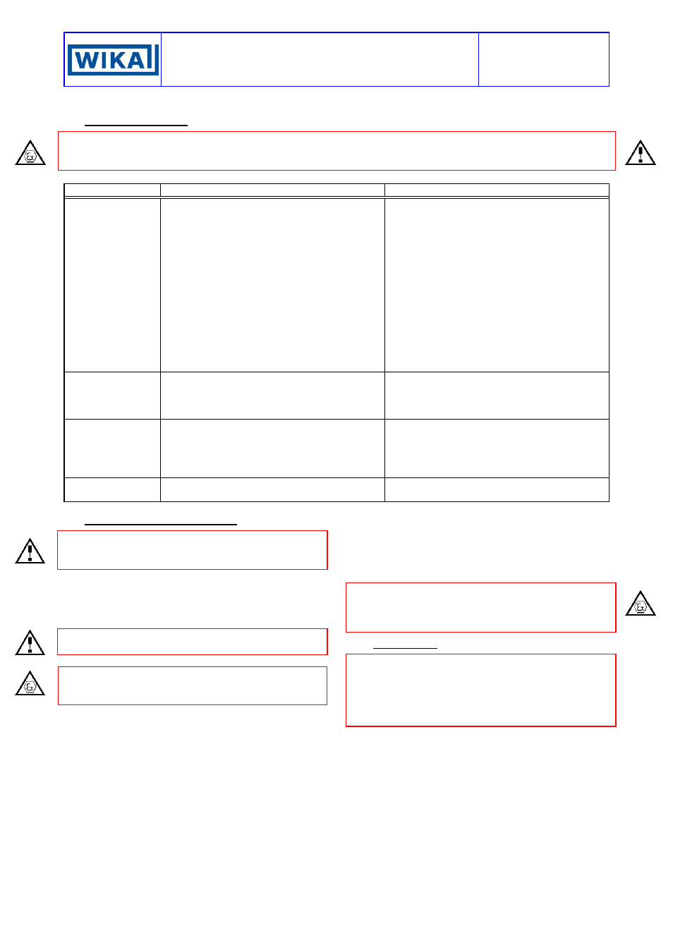
10. TROUBLESHOOTING
IMPORTANT NOTE: operations involving replacement of essential components must be carried out at our
workshop, especially for instruments with explosionproof certificate; this is to guarantee the user the total and
correct restoration of the product original characteristics.
MALFUNCTION PROBABLE
CAUSE
REMEDY
Set point shift
Air bubbles in the connection lines
(condensation in the case of use of gas;
excluding models DW10 and DA10)
Solid particles deposited inside the
measurement chambers of the instrument
(excluding models DW10 and DA10)
Permanent deformation of the sensitive
element due to fatigue or non-tolerated over-
ranges
Variation of the elastic features of the
sensitive element due to its chemical
corrosion.
Leakage of filling fluid (excluding models
DW10 and DA10).
Drain using the appropriate plugs
Dismount the measurement chambers and
clean them (during the mounting phase the
screw locking couple is 80 N/m)
Recalibrate or replace the sensitive element.
Recalibrate or replace the sensitive element
with another made of a suitable material. If
necessary apply a fluid separator
Send to the constructor for checking
Slow response
Clogged or obstructed connection line.
Root or service valve partially closed.
Too viscous fluid.
Check and clean line.
Open valve.
Provide instrument with suitable fluid
separator.
No actuation or
undue actuation
Root or service valve closed.
By-pass valve open.
Microswitch contacts damaged.
Loosened electrical joints.
Interrupted or short-circuited electrical line.
Open the valve.
Close the valve.
Replace the microswitch.
Check all electrical joints.
Check the conditions of the electrical line.
Undue actuation
Accidental shocks or excessive mechanical
vibrations.
Modify the mounting.
11. STOPPING AND DISMOUNTING
Before proceeding with these operations ensure that
the plant or machines have been put into the
conditions foreseen to allow these operations.
With reference to figures 7 and 8
Remove the power supply (signal) from the electrical
line.
Close the service valve (2) and open the by-pass valve.
Carefully open the drains.
Do not dispose of the process fluid into the environment,
if this can cause pollution or damage to people.
Unscrew the three piece joint (1).
CAUTION: do not open the cover of explosionproof
pressure switches (Series DA) when energized, in
explosive atmospheres.
Unscrew the three piece joint (11) (electrical cable
tubing).
Remove the instrument cover and disconnect the
electrical cables from the terminal block and earth
screws.
Remove the screws fixing the case to the panel (or pipe)
and remove the instrument, taking care to slide the
electrical conductors out from the case.
Replace the instrument cover. Insulate and protect the
conductors remaining on the plant. Temporarily plug the
pipes disconnected from the instrument.
In case of explosionproof instruments (Series DA) it is
recommended to follow - at least – the standard EN-
60079-17 for the withdrawal from service of electrical
apparatus.
12. DEMOLITION
The instruments are mainly made of stainless steel and
aluminium and therefore, once the electrical parts have
been dismounted and the parts coming into contact with
fluids which could be harmful to people or the
environment have been properly dealt with, they can be
scrapped.