Instruction manual ni-209e – WIKA DA10 User Manual
Page 4
INSTRUCTION MANUAL
NI-209E
Rev. 4 12/02
The test instrument should have a measurement range
approximately equal to or slightly wider than the
pressure switch range and should have an accuracy
consistent with the precision required to calibrate the set
point.
The pressure switch must be mounted in the normal
installation position, i.e. with the pressure connection
downwards; the instrument must be connected to the
pressure source by the + pipe inlet while the - pipe inlet
must be at atmospheric pressure.
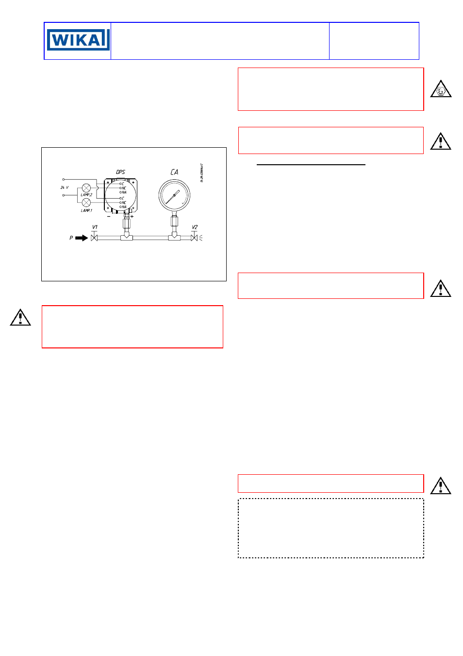
Fig. 5 -
Calibration circuit
DPS – Differential pressure switch
CA – Test pressure gauge
V1 - Inlet valve
V2 – Discharge valve
P - Pressure source
Test fluid:
air for P
≤ 10 bar
water for P > 10 bar
Avoid forcing the elastic support of the microswitch by
hand or with tools. This could affect the instrument
functioning.
CAUTION: if the switch is of the kind with adjustable
dead band (letter R of contacts code) before proceeding
with the following operations it is necessary to proceed
with the adjustment of the dead band (see attachment
NI-704E).
Increase the pressure in the circuit up to the desired set
point value for the first microswitch.
Use a wide bladed screwdriver, as indicated on the
adhesive plate, until the relative lamp turns on (or turns
off).
- If the instrument is equipped with only one contact the
calibration is complete.
- If it is equipped with two contacts continue in the
following manner.
Vary the pressure until the desired set point value for
the second microswitch is reached (fig. 2).
Act on the adjustment screw of the second contact.
Repeat former operations on the first contact, then
operations on the second contact, until the required set
point precision is obtained. This is necessary due to the
reciprocal influence which the microswitches have with
the sensitive element of the instrument.
Check the calibration values (varying the pressure in the
circuit accordingly) and record them on the adhesive
plate using a pen with indelible ink.
5.3 FINAL OPERATIONS
Disconnect the instrument from the calibration circuit.
Weatherproof pressure switches (Series DW)
Take the cover, ensure that the sealing gasket is
correctly fitted into its seat, insert the cover onto the
case, with the blocking gap positioned in
correspondence to the blocking bracket.
Turn the cover clockwise closing it tightly. Mount the
adjustment screw access plate, then the blocking device
as in Fig.3.
Explosionproof pressure switches (Series DA).
Insert the closure plugs of the adjustment screw access
holes, block them using the internal device and if
necessary seal them with plumbing. Screw on the cover
and block it using the headless screw with which it is
equipped (Fig. 4).
Replace the supplied protection caps on the pressure
attachment and cable conduit.
IMPORTANT: the protection caps should only be
definitively removed during the connection steps (see
§6).
6. MOUNTING AND CONNECTIONS
6.1 MOUNTING
Surface mount the instrument by means of the holes
provided, or pipe mount using the appropriate bracket
(see Fig. 9).
The chosen position must be such that vibrations, the
possibility of shocks or temperature changes are within
tolerable limits. With gas or vapour process fluid, the
instrument must be positioned higher than the pipe inlet
(see Fig. 8). With a liquid process fluid, the instrument
can be positioned higher or lower, indifferently (see
Fig.7 and 8).
6.2 PRESSURE CONNECTIONS
Connecting lines are an integral part of the instrument
in transmitting the measured variable from the
measuring point to the instrument.
For a correct installation it is necessary to:
Mount a shut-off valve with drain (root valve) on each
process pipe inlet to allow the instrument to be excluded
and the connection tubing to be drained. It is
recommended that said valve has a capstan blocking
device aimed at preventing it being activated casually
and without authorisation.
Mount a 3 valve manifold near the instrument to permit
possible functional verification on site and removal of
the instrument. It is recommended that the manifold is
made up of two service valves, one by-pass valve and
two suitably connected drain plugs. The three valves
with the drains can be reunited by a single device called
a “Three valve manifold”.
Mount a three piece joint onto the threaded attachment
of the instrument to permit the easy mounting or
removal of the instrument itself.
Carry out the connection using a flexible tube in such a
way that variations in the temperature of the tube itself
do not force the instrument attachment.
Ensure that all the pressure connections are airtight. It is
important that there are no leakage in the circuit.
Close root valves, the two service valves, drain plugs
and open the by-pass valve.
NOTE: if the instrument is used for level control in
tanks under pressure it is recommended that installation
is carried out according to the diagram in figure 8;
ensuring that:
• the distance K is greater than 0.5 m;
• the seal pot B has a sufficient capacity to maintain
the liquid level at the maximum height over time.