Gb 6. commissioning, operation – WIKA OT-1 User Manual
Page 11
11
WIKA operating instructions OEM pressure transmitter, model OT-1
2127027.02 09/2013 GB/D/F/E
GB
6. Commissioning, operation
6.2 Electrical mounting
6.2.1 Connection assembly
■
Use the pressure transmitter with shielded cable. The cable shield must be grounded, if the cable is longer than
30 m or leaves the building.
■
Use a cable with suitable characteristics for the particular operating conditions.
■
For cable variants, strain relief must be employed.
■
Cable with ventilation tubes must be vented to atmosphere.
■
The instrument must be grounded via the process connection.
■
Select a cable diameter that matches the cable gland of the plug. Make sure that the cable gland of the mounted
plug has a tight fit and that the seals are present and undamaged. Tighten the threaded connection and check that
the seal is correctly seated, in order to ensure the ingress protection.
■
For cable outlets, make sure that no moisture enters at the cable end.
■
This equipment is intended for operation with low voltages, which are separated from the power supply or voltages
of greater than AC 50 V or DC 120 V. Preferably, a connection to an SELV circuit is recommended, or alternatively to
circuits with a different protective measure in accordance with IEC 60364-4-41.
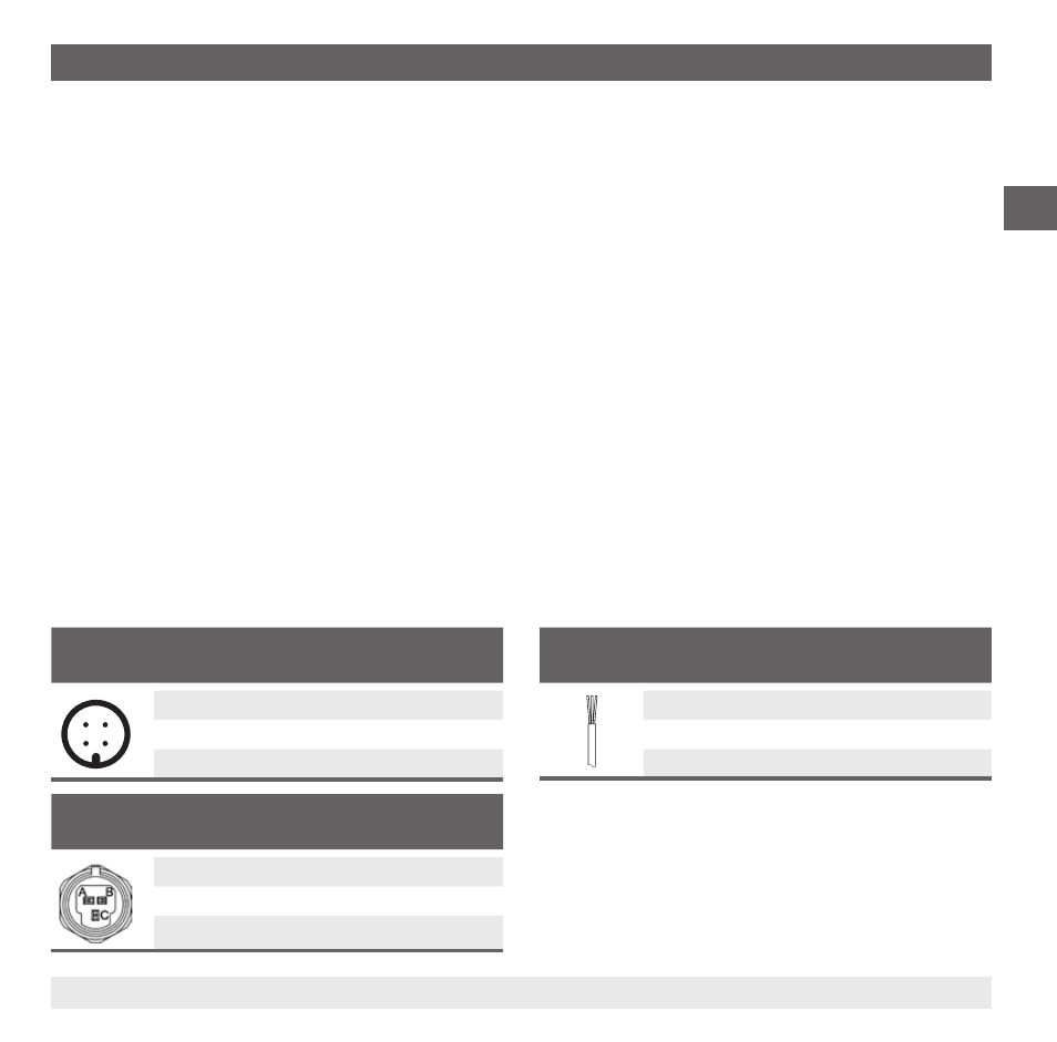
6.2.2 Connection diagrams
Circular connector M12 x 1 (4-pin)
2-wire
3-wire
4
3
1
2
U
+
1
1
U-
3
3
S
+
-
4
U+
Positive power supply
U-
Negative power supply, reference potential
S+
Positive output terminal
2-wire
The two connection lines are used for the voltage supply.
The measurement signal also provides the supply current.
3-wire
Two connection lines are used for the voltage supply.
One connection line is used for the measurement signal.
Cable outlet
2-wire
3-wire
U
+
brown
brown
U-
green
blue
S
+
-
white
Metri-Pack series 150 (3-pin)
2-wire
3-wire
U
+
B
B
U-
A
A
S
+
-
C