WIKA A2G-55 User Manual
Page 6
WIKA operating instructions air2guide model A2G-55
GB
Uv Out Gnd
Uv Out Gnd
Loop
6
40317650.01 09/2010 GB/D/F/E/I
5. Installation / 6. Commissioning / Electrical connections
6. Commissioning / Electrical connections
Output signal
DC 0 … 10 V, 3-wire
optionally 4 … 20 mA, 2-wire
Supply voltage
DC 13 ... 32 V
Electrical connection
PG-gland M16
Screw terminals max. 1.5 mm²
Connection diagram
5. Installation
■
Protect measuring instruments from contamination, high tempera-
ture changes and vibrations
■
In order to avoid any additional heating, the instruments must not be
exposed to direct solar irradiation while in operation.
■
The differential pressure transmitter must be screw-fitted on a
suitable vertical surface. The instrument has to be mounted horizon-
tally using the enclosed mounting screws.
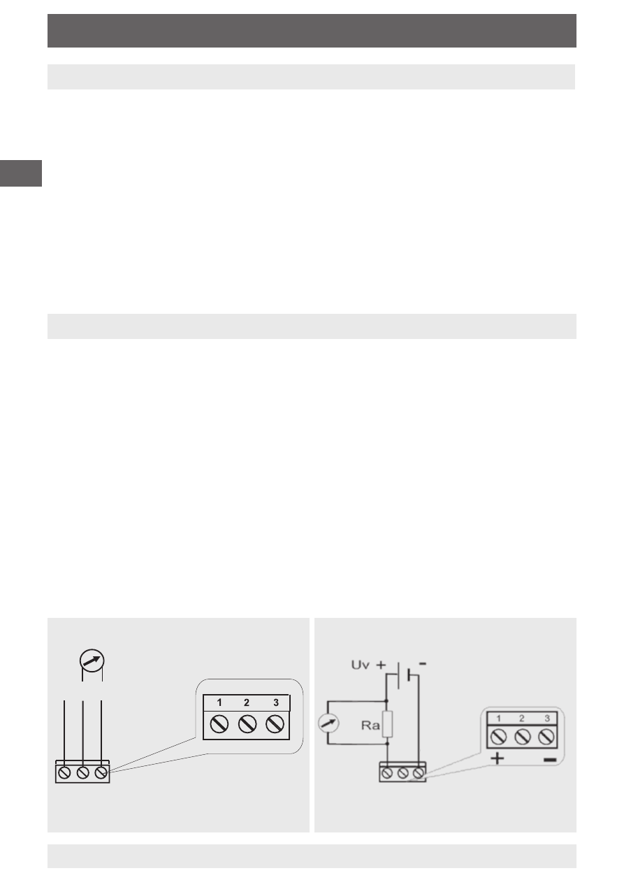
Legend
Pin 1: Power supply (+)
Pin 2: Output signal
Pin 3: Ground
Legend
Pin 1: Loop +
Pin 3: Loop -
Output signal 4 … 20 mA, 2-wire
Output signal DC 0 … 10 V, 3-wire