WIKA 890.09.2190 User Manual
Page 10
10
GB
WIKA operating instructions differential pressure transmitter model 890.09.2190
11171545.02 08/2010 GB/D/F/E
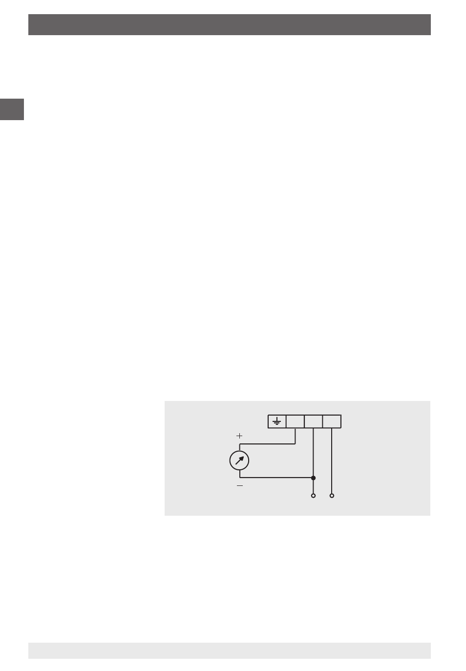
1 ... black
2 ... blue
3 ... brown
4 ... 20 mA
1
-2
+3
DC 24 V
6. Commissioning, operation
connector on the instrument.
By applying slight pressure the cable snaps into the connector. Screw the cable
gland to the case. Then the internal sealing of the cable gland is press-fitted to the
cable.
When mounting the instrument, ensure that the air filter will not become clogged
by dust or liquid.
Opening the case is not allowed, as this will lead to permanent instrument
damage.
Process connection
When connecting the instrument, the lines must be free of pressure.
The instrument must be protected from pressure spikes by taking appropriate
measures
Only for operation with suitable media
Observe maximum pressure
Observe the permissible overpressure
The pressure connections are marked with ⊕ and ⊖ symbols on the instrument.
For differential pressure measurements, the higher pressure should be connected
to the ⊕ side and the lower pressure to the ⊖ side of the instrument.
Electrical connection
The electrical connection of the instrument must be carried out in accordance
with both the applicable codes and standards (VDE regulations) and the local
power supply company's regulations
Before connecting the instrument the plant must be electrically isolated
Safety fuses should be series-connected and sized appropriately for the power
rating
The instrument has a
3-wire connection and its
electrical connection is
detailed in the illustration.
Commissioning
Before commissioning, the instrument and all electrical wiring must be properly
installed. All connection lines must be run so that no mechanical forces will act
on the instrument.
The pressure measuring lines should be constructed so that a sufficient gradient
exists, so that, for example, no air pockets can occur when measuring liquids
nor water pockets when measuring gases. If the gradient required cannot be
achieved, water or air separators must be fitted at the appropriate points.