Kramer Electronics TP-43 User Manual
Page 9
Connecting the TP-43 Component – S/PDIF Transceiver
5
4.2 Your TP-43 Component – S/PDIF Transceiver Underside
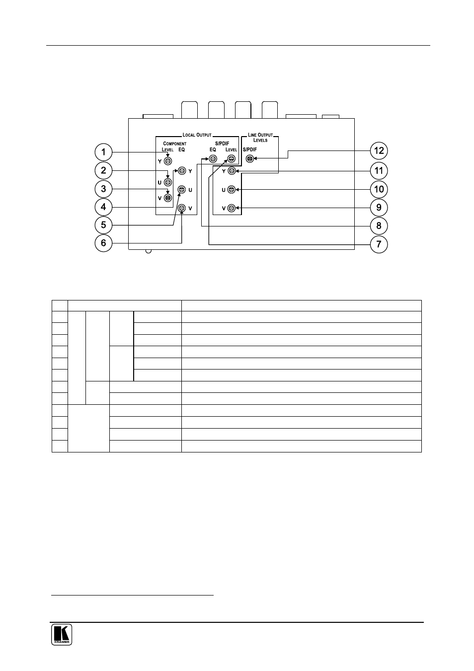
Figure 4 and Table 2 define the underside of the
TP-43:
Figure 4: TP-43 Component – S/PDIF Transceiver Underside
Table 2: TP-43 Component – S/PDIF Transceiver Underside Features
#
Feature
Function
1
Y Trimmer Adjusts
1
the Y output signal level
2
U Trimmer Adjusts
1
the U output signal level
3
LE
V
E
L
V Trimmer Adjusts
1
the V output signal level
4
Y Trimmer Adjusts
1
the cable compensation equalization level for output Y
5
U Trimmer Adjusts
1
the cable compensation equalization level for output U
6
C
O
M
P
O
N
E
N
T
E
Q
.
V Trimmer Adjusts
1
the cable compensation equalization level for output V
7
LEVEL
Adjusts
1
the digital audio signal level
8
LO
C
A
L
O
U
TP
U
T
S/
PD
IF
EQ.
Adjusts
1
the digital audio output cable compensation equalization level
9
V Trimmer
Adjusts
1
the V line output signal level
10
U Trimmer
Adjusts
1
the U line output signal level
11
Y Trimmer
Adjusts
1
the Y line output signal level
12
LI
N
E
O
U
TP
U
T
LE
V
E
LS
S/PDIF Trimmer
Adjusts
1
the S/PDIF digital audio line output signal level
5
Connecting the TP-43 Component – S/PDIF Transceiver
This section describes how to connect:
The
TP-43, see section 4.1
An extended Component – S/PDIF distribution system by
connecting three
TP-43 units between the TP-41 and the TP-42,
see section 4.2
1 Insert a screwdriver into the small hole and carefully rotate it, trimming the level