Kramer Electronics TP-42 User Manual
Page 7
Your Component – S/PDIF Line Transmitter and Line Receiver
5
4.1.1
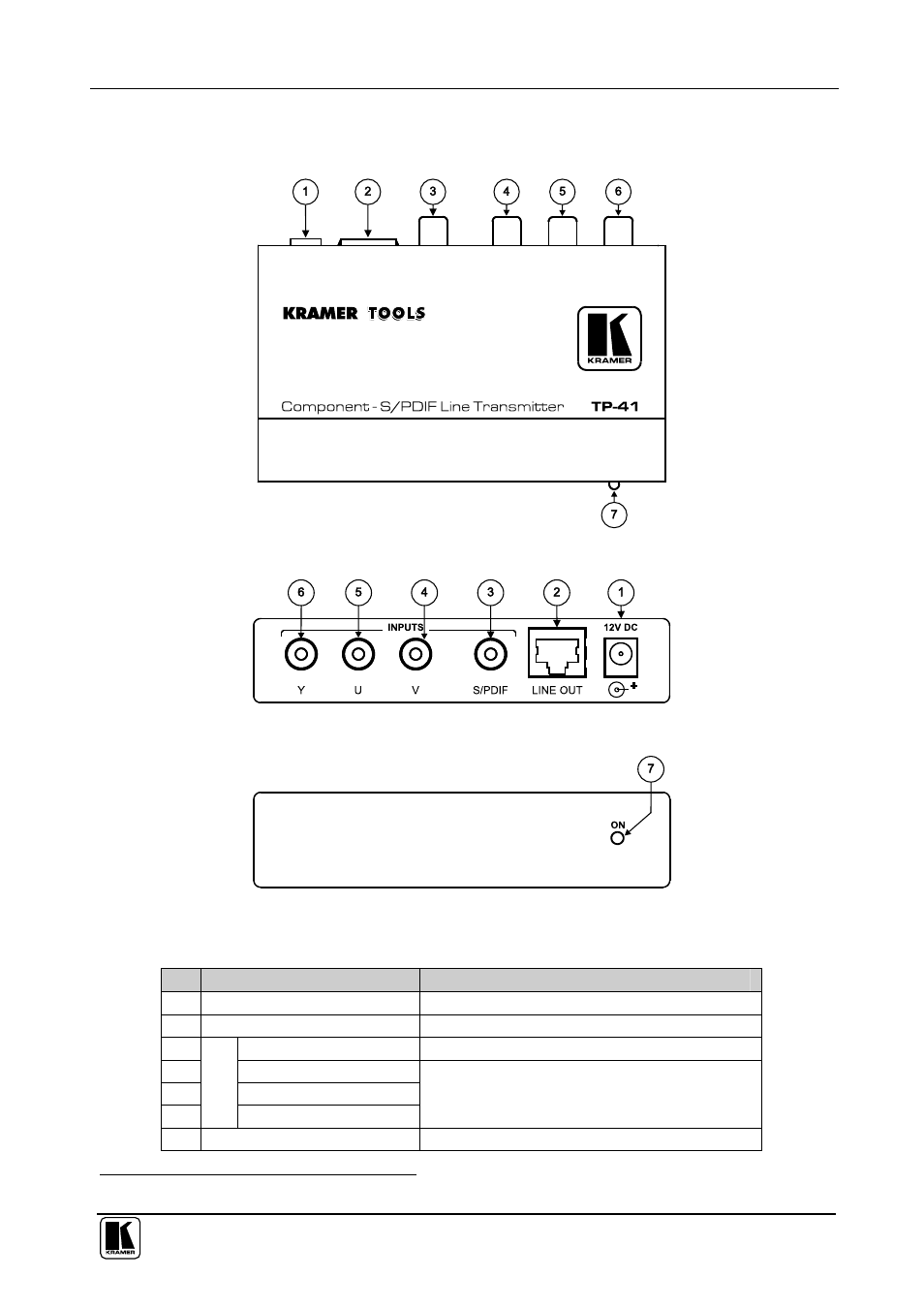
Your TP-41 Component – S/PDIF Line Transmitter Topside
Figure 1, Figure 2, Figure 3 and Table 1 define the
TP-41:
Figure 1: TP-41 Component – S/PDIF Line Transmitter
Figure 2: TP-41 Component – S/PDIF Line Transmitter (Top Side Panel)
Figure 3: TP-41 Component – S/PDIF Line Transmitter (Lower Side Panel)
Table 1: TP-41 Component – S/PDIF Line Transmitter Features
#
Feature
Function
1
12V DC
+12V DC connector for powering the unit
2
LINE OUT RJ-45 Connector
Connects to the LINE IN connector on the TP-42
1
3
S/PDIF RCA Connector Connects to the digital audio source
4
V RCA Connector
5
U RCA Connector
6
IN
P
U
TS
Y RCA Connector
Connects to the component video source
7
ON LED
Illuminates when receiving power
1 Using a straight pin to pin UTP cable with RJ-45 connectors at both ends (the PINOUT is defined in Table 5 and Figure 10)