Kramer Electronics TP-100 User Manual
Page 7
KRAMER: SIMPLE CREATIVE TECHNOLOGY
Your XGA Line Transmitter and the XGA Line Receiver
4
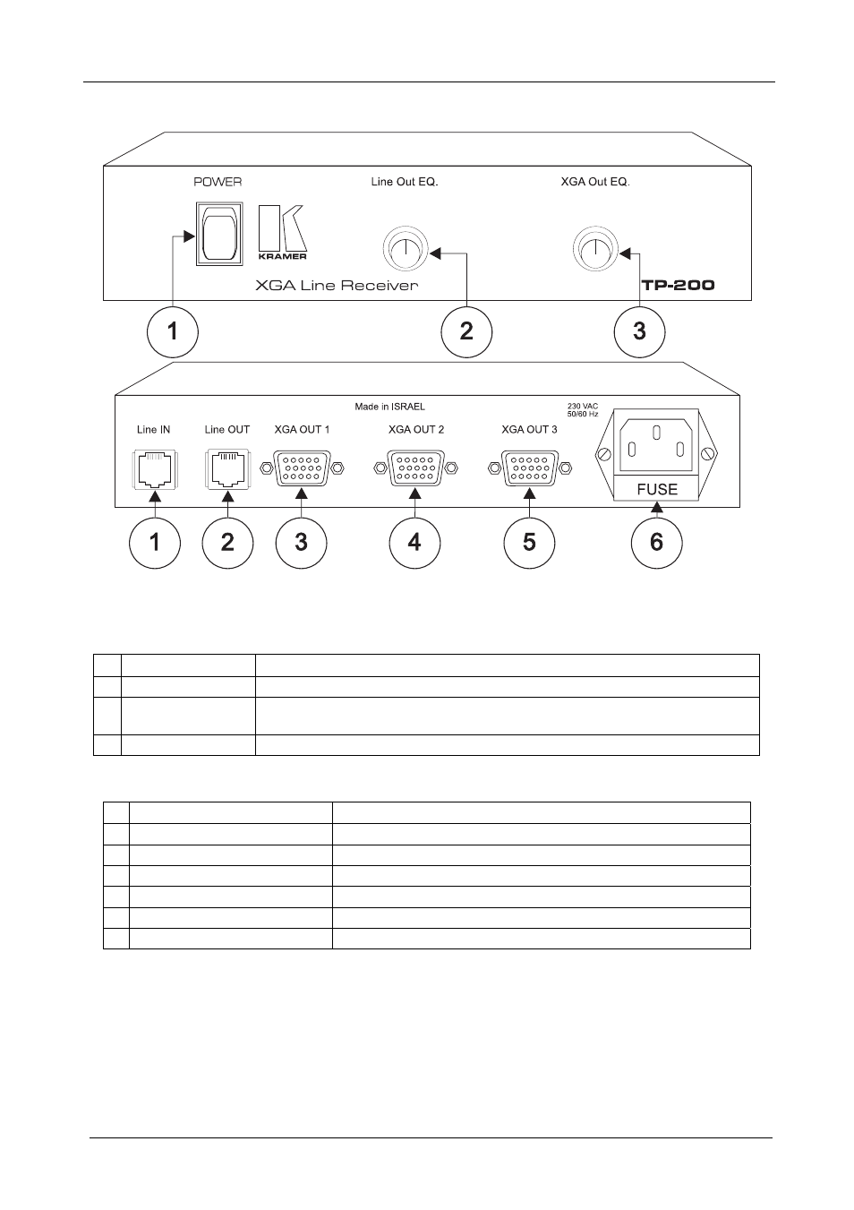
Figure 2, Table 3 and Table 4 define the TP-100:
Figure 2: TP-200 XGA Line Receiver
Table 3: Front Panel TP-200 XGA Line Receiver Features
# Feature
Function
1
POWER Switch
Illuminated switch supplying power to the unit
2
Line Out EQ. Knob Adjusts the equalization control level (EQ.) for the signal transmitted via the
CAT5 Line output to the next XGA Line Receiver
3
XGA Out EQ. Knob Adjusts the equalization control level (EQ.) for the decoded XGA signal
Table 4: Rear Panel TP-200 XGA Line Receiver Features
# Feature
Function
1
Line IN CAT5 Connector
Connects to the Line OUT connector on the XGA Line Transmitter
2
Line OUT CAT5 Connector
Connects to the Line IN connector on the next XGA Line Receiver
3
XGA OUT 1 HD15 Connector Connects to the video acceptor 1
4
XGA OUT 2 HD15 Connector Connects to the video acceptor 2
5
XGA OUT 3 HD15 Connector Connects to the video acceptor 3
6 Power
Connector
with
FUSE
AC connector enabling power supply to the unit