Kramer Electronics TP-100 User Manual
Page 6
Your XGA Line Transmitter and the XGA Line Receiver
3
4 Your XGA Line Transmitter and the XGA Line Receiver
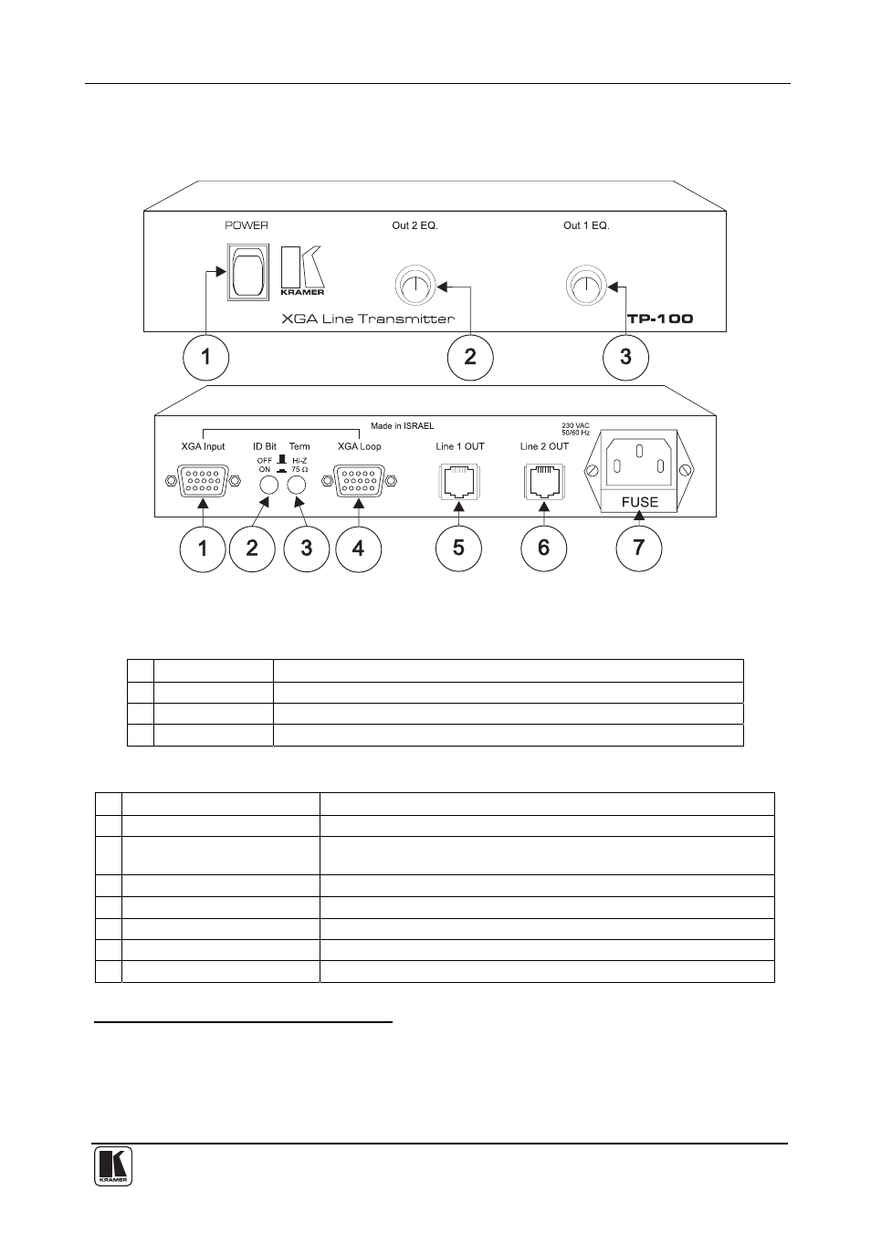
Figure 1, Table 1 and Table 2 define the TP-100:
Figure 1: TP-100 XGA Line Transmitter
Table 1: Front Panel TP-100 XGA Line Transmitter Features
# Feature
Function
1
POWER Switch
Illuminated switch supplying power to the unit
2
Out 2 EQ. Knob
Adjusts the equalization control level (EQ.) for the CAT5 Line 2 output
3
Out 1 EQ. Knob
Adjusts the equalization control level (EQ.) for the CAT5 Line 1 output
Table 2: Rear Panel TP-100 XGA Line Transmitter Features
# Feature
Function
1
XGA Input HD15 Connector
Connects to the video source
2
ID Bit (OFF / ON) Button
Pushing in selects the ID BIT (when outputting a VGA signal from a
laptop to an external VGA monitor
1
); releasing deactivates the ID BIT
3
Term (Hi-Z / 75
Ω
) Button
Pushing in selects 75
Ω
; releasing selects Hi-Z
2
4
XGA Loop HD15 Connector
For looping to a VGA acceptor
5
Line 1 OUT CAT5 Connector Connects to the Line IN connector on the TP-200 XGA Line Receiver
3
6
Line 2 OUT CAT5 Connector Connects to the Line IN connector on the TP-200 XGA Line Receiver
3
7 Power
Connector
with
FUSE AC connector enabling power supply to the unit
1 Sometimes laptop computers refuse to output a VGA signal to an external VGA monitor. By setting the ID Bit to ON (and
using pin # 4 on the VGA connector that is normally unused), the laptop computer will output to an external VGA monitor
2 For looping select Hi-Z
3 Using a UTP cable with CAT5 connectors at both ends