1 your tp9 audio/video line transmitter, Your tp-9 audio/video line transmitter, Figure 1: tp-9 audio/video line transmitter – Kramer Electronics TP-9 User Manual
Page 7: Table 1: features and functions of the tp-9
Your Audio/Video Line Transmitter and Line Receiver
5
4 Your
Audio/Video Line Transmitter and Line Receiver
This section describes the:
• TP-9 Audio/Video Line Transmitter, see section
• TP-10 Audio/Video Line Receiver, see section
4.1
Your TP-9 Audio/Video Line Transmitter
and
define the TP-9 unit:
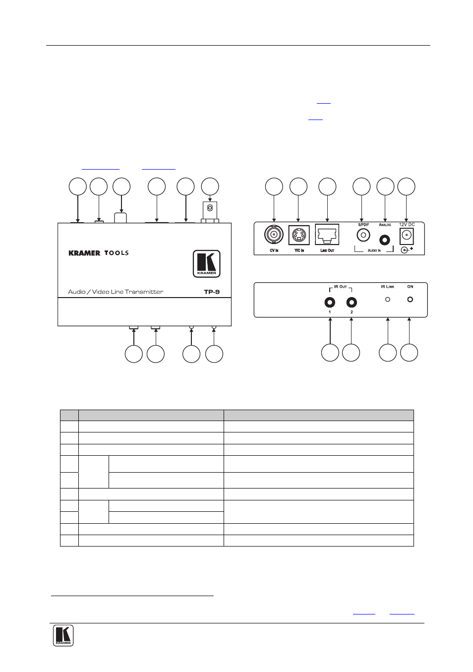
Figure 1: TP-9 Audio/Video Line Transmitter
Table 1: Features and Functions of the TP-9
#
Feature
Function
1
CV IN BNC Connector
Connects to the composite video source
2
Y/C IN 4-pin Connector
Connects to the s-Video source
3
LINE OUT RJ-45 Connector Connects
to
the
LINE IN connector on the TP-10
4
AUDIO
IN
S/PDIF RCA Connector
Connects to the digital audio source
5
ANALOG 3.5mm Mini connector Connects to the analog audio source
6
12V DC
+12V DC connector for powering the unit
7
IR
OUT
3.5mm Mini connector 1
Connects to the IR emitter cable
8 3.5mm
Mini
connector
2
9
IR LINK LED
Lights when an IR link is established
10 ON LED
Lights when receiving power
1 Using a straight pin to pin UTP cable with RJ-45 connectors at both ends (the PINOUT is defined in
Table 4
and
Figure 6
)
1
1
4
4
9
9
2
2
5
5
8
8
3
3
10
10
6
6
7
7