5 connecting an audio/video distribution system, Connecting an audio/video distribution system, Figure 4: connecting the ir emitter – Kramer Electronics TP-9 User Manual
Page 10
KRAMER: SIMPLE CREATIVE TECHNOLOGY
Connecting an Audio/Video Distribution System
8
5
Connecting an Audio/Video Distribution System
To configure a TP-9/TP-10 audio/video distribution system (for example,
for high quality home cinema system), as
illustrates, do the following:
1. On
the
TP-9 connect:
A composite video source (for example, a video player) to the CV
IN BNC connector
A digital audio source (for example, the video player’s audio
signal) to the AUDIO IN S/PDIF RCA connector
The IR OUT 2, 3.5mm mini connector to the IR receiver
(on the
video player) via the IR emitter cable (see
)
2. On
the
TP-10, connect the:
CV OUT BNC connector to a composite video acceptor (for
example, a plasma display)
AUDIO OUT S/PDIF (digital audio) RCA connector
to an audio
acceptor (for example, the plasma display’s audio connector)
3. Connect the LINE OUT connector of the TP-9 to the LINE IN connector of
the TP-10, via UTP cabling (maximum range of up to 300ft (100m)).
4. On
the
TP-9 underside, set the VIDEO switch to CV and the AUDIO
switch to S/PDIF.
Note: Do not power the device ON when set to S/PDIF. First set the device
to Analog mode, power on and then switch to S/PDIF if needed.
5. On
each
TP-9/TP-10 unit, connect a 12V DC power adapter to the power
socket and connect the adapter to the mains electricity (see section
6. On
the
TP-10, if required, adjust the CV EQ. and level, by inserting a
screwdriver into the small hole and carefully rotating it.
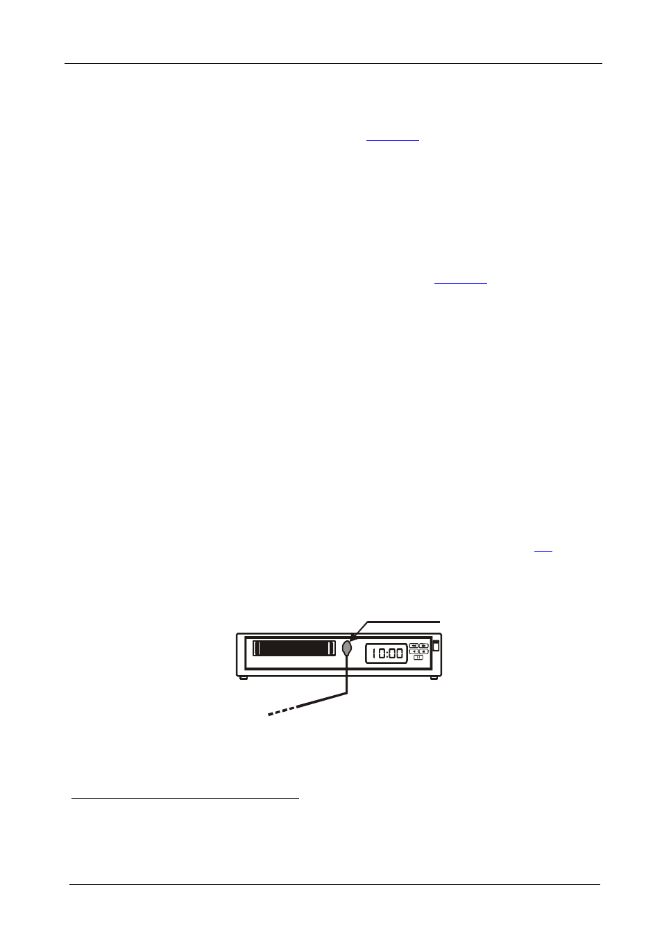
Figure 4: Connecting the IR Emitter
1 Stick the IR emitter to the IR receiver window (usually located on the front panel of the video player)
2 You can also connect either the AUDIO OUT ANALOG 3.5mm mini connector to an analog audio acceptor, or both
AUDIO OUT connectors
IR Emitter