2 connecting an ir receiver and emitter, Wiring the cat 5 line in/line out rj-45 connectors, Connecting an ir receiver and emitter – Kramer Electronics WP-562 User Manual
Page 19: Figure 10: cat 5 pinout, Table 5: cat 5 pinout, Section, Cat 5 cables and the ir emitter
KRAMER: SIMPLE CREATIVE TECHNOLOGY
Connecting the PT-561 and PT-562
16
7.1
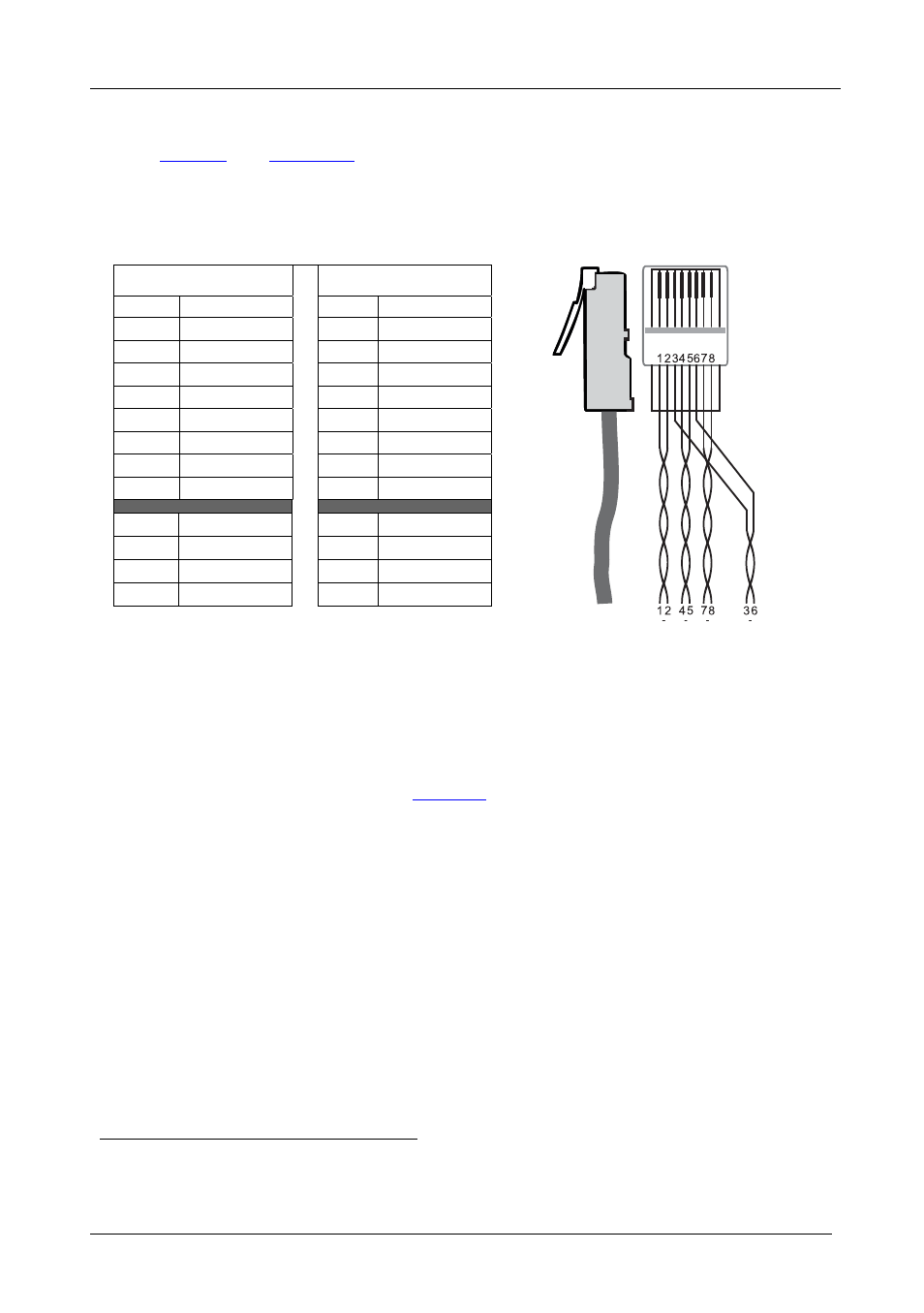
Wiring the CAT 5 LINE IN/LINE OUT RJ-45 Connectors
define the CAT 5 pinout, using a straight pin-to-pin
cable with RJ-45 connectors (note, that the cable Ground shielding must be
connected/soldered to the connector shield):
Table 5: CAT 5 PINOUT
Figure 10: CAT 5 PINOUT
EIA /TIA 568A
EIA /TIA 568B
PIN
Wire Color
PIN
Wire Color
1 Green/White 1 Orange/White
2 Green
2 Orange
3 Orange/White
3 Green/White
4 Blue
4 Blue
5 Blue/White 5 Blue/White
6 Orange
6 Green
7 Brown/White 7 Brown/White
8 Brown
8 Brown
Pair 1
4 and 5
Pair 1
4 and 5
Pair 2
3 and 6
Pair 2
1 and 2
Pair 3
1 and 2
Pair 3
3 and 6
Pair 4
7 and 8
Pair 4
7 and 8
7.2
Connecting an IR Receiver and Emitter
You can control the source or the acceptor by connecting an IR emitter
cable and an IR receiver cable to the 3.5mm mini jacks on the transmitter
and receiver.
In the example illustrated in
, the display can be controlled from a
distance by transmitting the IR signal from the display remote control via
the IR Receiver
, CAT 5 cables and the IR emitter
which is attached to the
IR sensor window of the display.
Alternatively, you can control the DVD player by sticking the IR LED of
the IR emitter to the IR sensor window of the DVD player, and connecting
it to the PT-561. The IR Receiver is connected to the PT-562, letting you
control the DVD player from a distance via the CAT 5 cables.
1 For example, the Kramer C-A35M/IRR IR Receiver
2 For example, the Kramer C-A35M/IRE IR Emitter