Figure 2: fc-50, Rs-232 range extender underside, Table 1: fc-50 – Kramer Electronics FC-50 User Manual
Page 7: Rs-232 range extender features, Table 2: fc-50, Rs-232 range extender underside features, Table 1, Figure 2 and table 2 define the fc-50 underside
Your FC-50 RS-232 Range Extender
5
5
Table 1: FC-50 RS-232 Range Extender Features
#
Feature
Function
1
12V DC
+12V DC connector for powering the unit
2
CAT 5 RJ-45 Connector
Connect to
3
the CAT 5 RJ-45 connector on the other
FC-50 unit
PC / DEVICE Button
Press when a device is connected to the RS-232 port
Release when a PC is connected to the RS-232 port
4
RS-232 9-pin D-sub
Connector
Connects to either a PC or a device
PINs 2, 3 and 5 are passed through the device
5
GREEN=PC
RED=DEVICE
LED
Lights in green when the PC/DEVICE button is released and in red
when the PC/DEVICE button is pressed
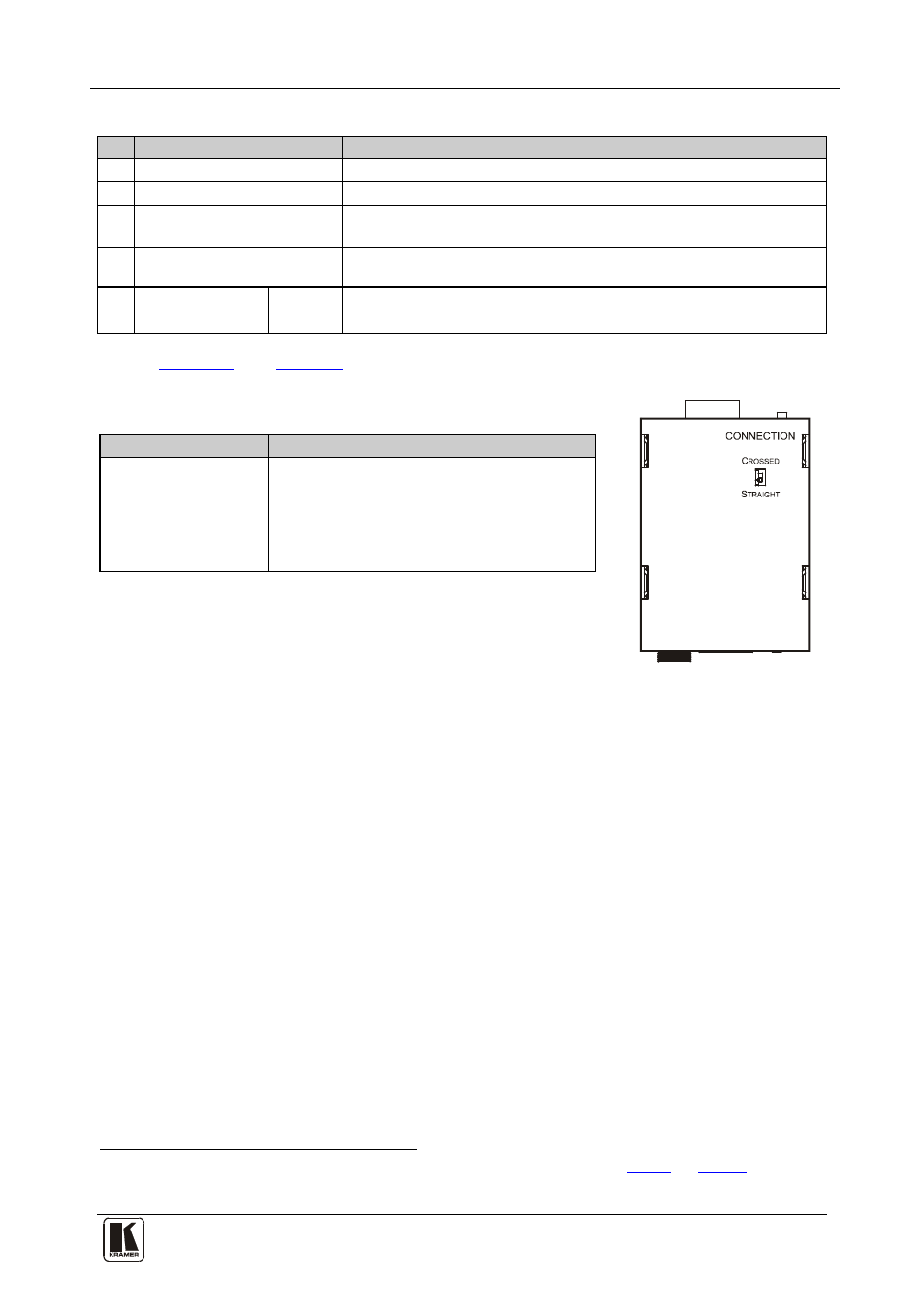
Table 2: FC-50 RS-232 Range Extender Underside Features
Figure 2: FC-50 RS-232
Range Extender Underside
Feature
Function
CROSSED /
STRAIGHT
CONNECTION Switch
Set to CROSSED for a crossed wire
connection
Set to STRAGHT for a straight wire
connection between the RS-232 port and the
PC/device
between the RS-232 port and the
PC/device
1 Using a UTP CAT 5 cable with RJ-45 connectors at both ends (the PINOUT is defined in
2 PINs 2 and 3 (Rx and Tx) are crossed in the wiring between the 9-pin D-sub connectors