Figure 4: cat 5 pinout – Kramer Electronics 712N User Manual
Page 12
711N, 712N - Connecting the 711N and the 712N
9
9
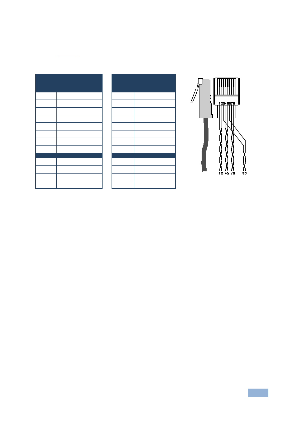
5.1 Wiring the CAT 5 LINE IN / LINE OUT RJ-45 Connectors
defines the UTP CAT 5 PINOUT, using a straight pin to pin
cable with
RJ-45 connectors:
Figure 4: CAT 5 PINOUT
Feature
EIA /TIA 568B
PIN
Wire Color
PIN
Wire Color
1
Green / White
1
Orange / White
2
Green
2
Orange
3
Orange / White
3
Green / White
4
Blue
4
Blue
5
Blue / White
5
Blue / White
6
Orange
6
Green
7
Brown / White
7
Brown / White
8
Brown
8
Brown
Pair 1 4 and 5
Pair 1
4 and 5
Pair 2 3 and 6
Pair 2
1 and 2
Pair 3 1 and 2
Pair 3
3 and 6
Pair 4 7 and 8
Pair 4
7 and 8
This manual is related to the following products: