2 dip-switch settings, Dip-switch settings, Table 3: dip-switch settings – Kramer Electronics SP-11D User Manual
Page 13: Table 4: test signals, Set dipswitch 2 on (see, Table 3, For details), Connecting your sp-11d digital video processor
Connecting Your SP-11D Digital Video Processor
11
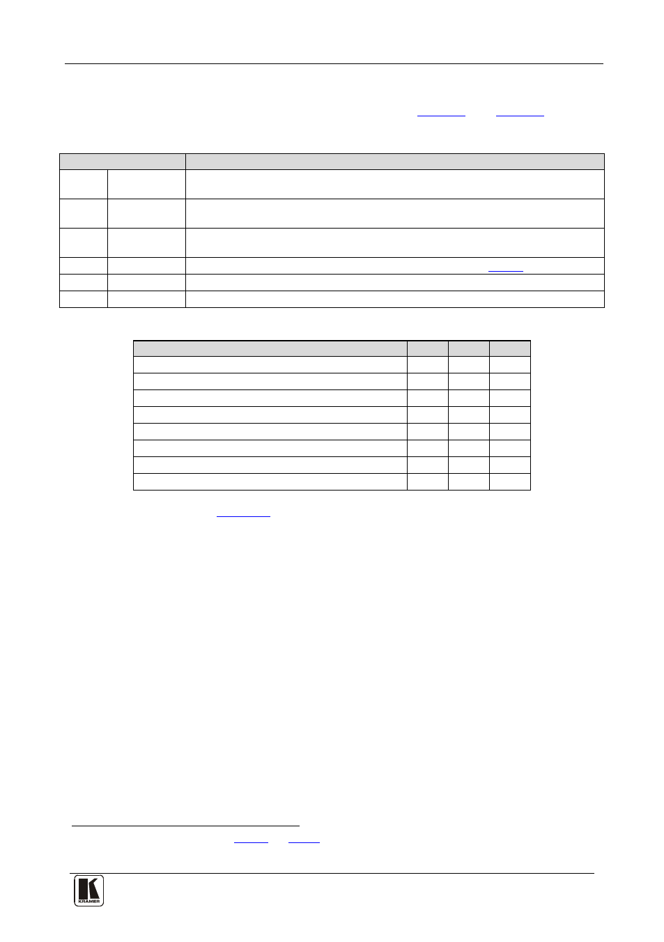
6.2 DIP-Switch Settings
The SP-11D DIP-switch settings are defined in
Table 3: DIP-switch Settings
DIP-Switch
Set as follows:
1
Pedestal
ON for pedestal of output signal (7.5 IRE offset selection for NTSC); OFF for no
pedestal
2
HsVs/Cs1
ON for Composite Sync on outputs Hs/Cs and Vs/Cs; OFF for Horizontal Sync on
Hs/Cs, and Vertical Sync on Vs/Cs outputs
3
Secam VBI
ON for insert identification signals occupying 9 lines of field-blanking period (only for
SECAM output standard) (bottle pulses); OFF for no insert (no bottle pulses)
4, 5, 6 Test Signals The status of these DIP-switches defines the test signal: see
7
AGC
ON for enabling automatic gain control; OFF for disabling automatic gain control
8
ADDR
For selecting one of two machine addresses (defining the machine address)
Table 4: Test Signals
FUNCTION
DIP 4 DIP 5 DIP 6
VITS 330 (Modulated Staircase) – full field mode
ON
ON
ON
No Signal
OFF
OFF
OFF
Split 75% Bar Generator
ON
ON
OFF
VITS 18 (Multiburst 5.8MHz) – full field mode
ON
OFF
ON
Vertical 75% Bar Generator
ON
OFF
OFF
Inverse Horizontal 75% Bar Generator
OFF
OFF
ON
Horizontal 75% Bar Generator
OFF
ON
OFF
VITS 17 (2T, 20T, 5 Step Staircase) – full field mode OFF
ON
ON
The example in
illustrates how to connect your SP-11D:
1 See the rear panel items 15 and 14 in
2 This is the Main mode; test signals are not available