Figure 3: connecting the wp-500 front panel, Figure 3 – Kramer Electronics WP-500 User Manual
Page 8
KRAMER: SIMPLE CREATIVE TECHNOLOGY
Using Your WP-500
6
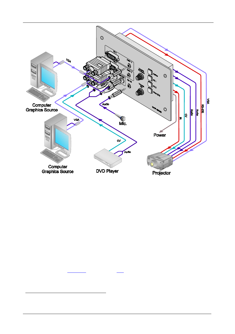
Figure 3: Connecting the WP-500 Front Panel
2. On the rear panel, connect the display device (for example, a projector) as
follows. Connect the:
VGA (PC) OUTPUT to the PC Graphics (15-pin HD connector or
RGBHV connector) input on the projector
VIDEO OUT output (VIDEO OUT, GND) to the video input on the
projector
AUDIO OUT 1 and AUDIO OUT 2 outputs to the audio input of the
video and PC inputs on the projector
RS-232 port to the PC control port of the projector and/or the IR OUT to
the IR receiver of the projector
3. Connect the ETHERNET port to a PC for configuration and control (not
shown in
), see section
1 You can connect either AUDIO OUT 1 or AUDIO OUT 2 to either the PC or the CV input of the projector since both audio
outputs are identical
- VM-114H (22 pages)
- VM-114H2C (25 pages)
- VM-114H4C (23 pages)
- VS-81ETH (27 pages)
- VS-81ETH (41 pages)
- VM-9T (13 pages)
- VP-12NHD (15 pages)
- VP-5R (20 pages)
- VP-6A (15 pages)
- PT-5R/T (13 pages)
- TP-102HD (13 pages)
- TP-104HD (33 pages)
- TP-112HD (13 pages)
- TP-114 (13 pages)
- TP-202 (15 pages)
- TP-205A (15 pages)
- TP-210 (14 pages)
- TP-210A (15 pages)
- tp-219hd (16 pages)
- TP-305A (15 pages)
- TP-310A (18 pages)
- TP-410 (34 pages)
- VM-1H4C (17 pages)
- VP-200xlT (31 pages)
- VP-300THD (12 pages)
- VPM-2 (42 pages)
- SI-1VGA (2 pages)
- SID-DP (2 pages)
- SID-DVI (2 pages)
- SID-H (2 pages)
- SID-VGA (2 pages)
- SID-X1 (2 pages)
- SID-X1 (23 pages)
- SID-X1N (23 pages)
- SID-X2N (31 pages)
- SID-X3N (22 pages)
- 622R (17 pages)
- VS-169TP (7 pages)
- VS-169TP (45 pages)
- WSI-1VGA (2 pages)
- TP-107AV (32 pages)
- RC-62 (94 pages)
- RC-5B2 (137 pages)
- WP-500 (2 pages)
- SV-552 (22 pages)